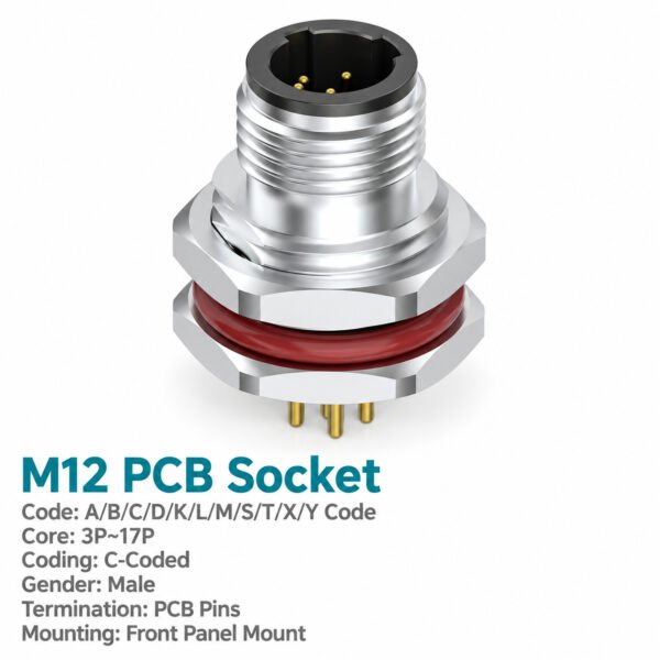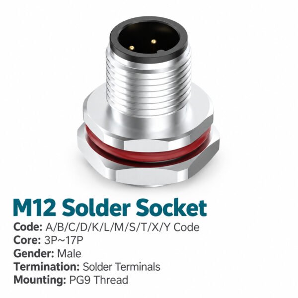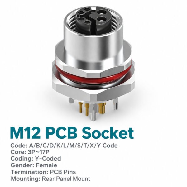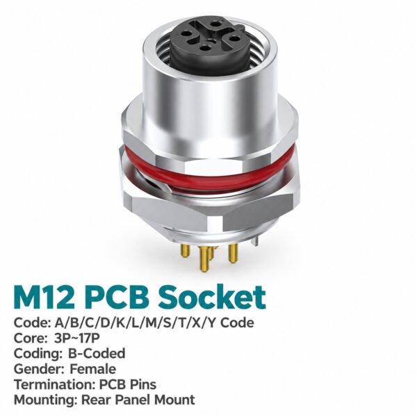
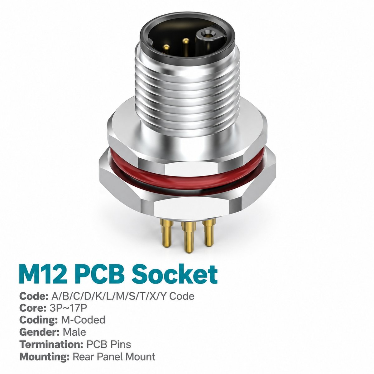
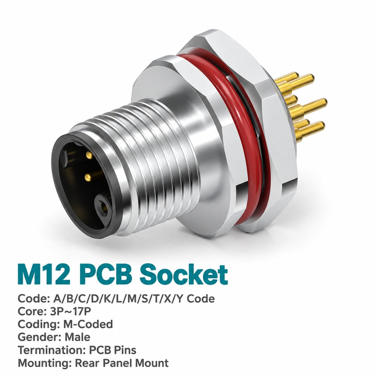
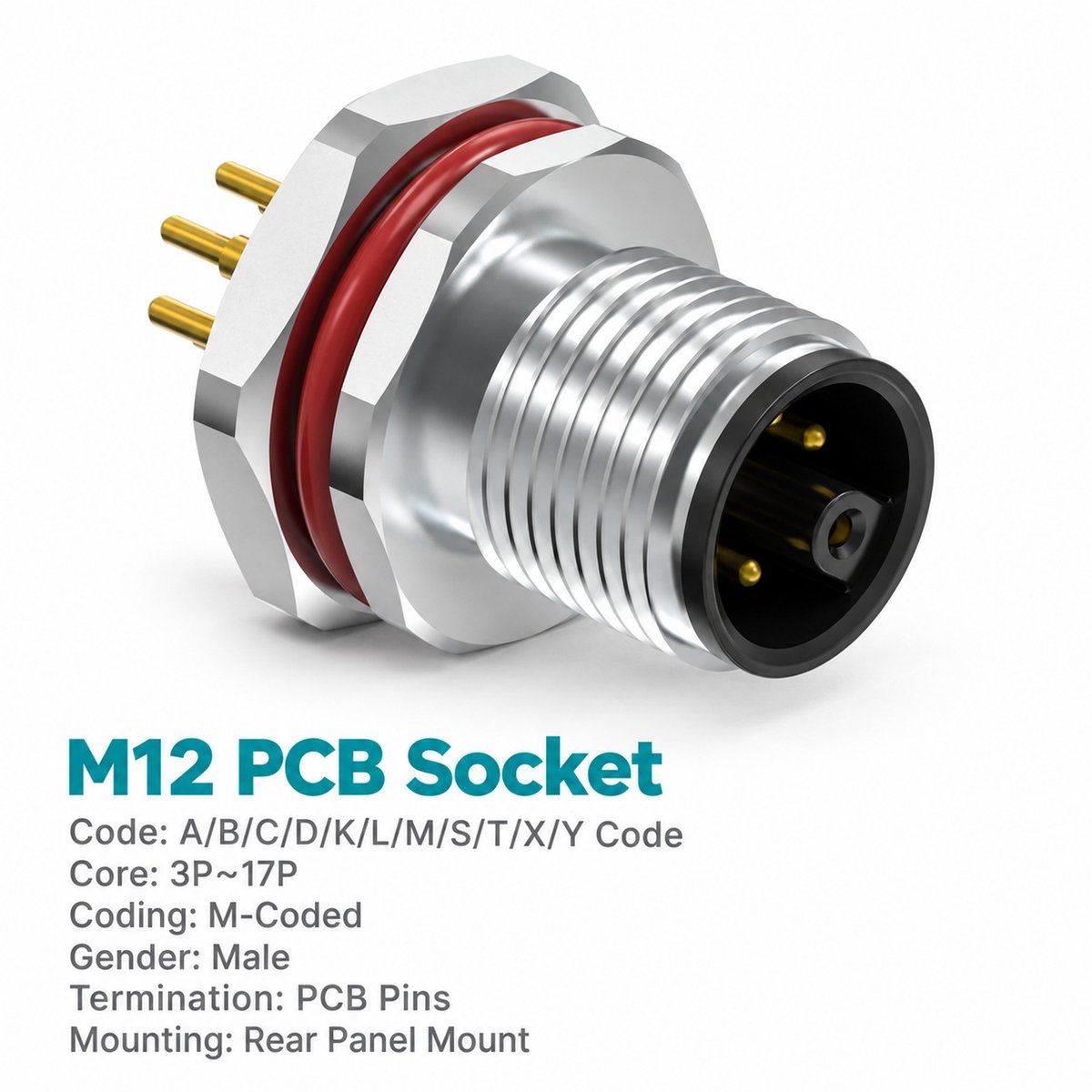
Xmost M12 M-coded female rear mount PCB socket links an external AC power cable to the circuit board inside industrial equipment. Its female interface receives a compatible M-coded male connector, while straight rear contacts provide PCB dip-solder termination.
Designed for rear fastened installation, this M12 panel mount power socket suits enclosures with a defined panel-to-board position. Use the rear mount outline to check mounting clearance and circuit-board placement.
Four contact configurations include protective earth, ranging from 2+PE to 5+PE. Each carries catalogue ratings of 8 A and 630 V. Select the required arrangement together with PG9 or M16 × 1.5 panel mounting.
Key Features
- Rear fastened construction: For housings designed around a rear mount panel power socket.
- Female M12 M-coded interface: Mates with compatible male AC power cable connectors.
- 8 A / 630 V ratings: Listed for all four contact arrangements.
- Protective earth included: Two to five circuit contacts plus PE.
- Direct PCB termination: Straight insertion contacts support dip soldering.
- PG9 or M16 × 1.5 mounting: Two panel thread options in unshielded construction.
Product Dimensions
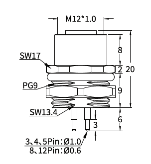
[Insert the female rear mount outline drawing and corresponding panel cut-out drawing from page 21.]
Illustrated PG9 Rear Mount Version — Dimensions in mm
| Item | Drawing Value |
|---|---|
| Mating thread | M12 × 1.0 |
| Panel mounting thread shown | PG9 |
| Body dimension shown, excluding PCB contacts | 20 |
| Upper axial section | 8 |
| Flange section | 2 |
| Lower axial section | 9 |
| Upper wrench size | SW17 |
| Lower wrench size | SW13.4 |
| Rear contact section | 6 |
| Contact tip section | 3 |
| PCB contact diameter indicated for 3 / 4 / 5-pin versions | Ø1.0 |
The outline drawing does not separately specify the 6-pin PCB contact diameter.
Needle Arrangement (Front View)

[Insert the M-coded female needle arrangement diagrams for 3-pin (2+PE), 4-pin (3+PE), 5-pin (4+PE) and 6-pin (5+PE) from page 21.]
| Total Contacts | Arrangement |
|---|---|
| 3 pins | 2+PE |
| 4 pins | 3+PE |
| 5 pins | 4+PE |
| 6 pins | 5+PE |
The diagrams show the female connector from the mating face. Identify the numbered contacts and PE position using the selected arrangement, then follow the equipment schematic for circuit connections.
Product Specifications
| Parameter | Specification |
|---|---|
| Product type | M12 M-coded female rear mount PCB AC power socket |
| Mounting | Rear fastened |
| Contact arrangements | 2+PE / 3+PE / 4+PE / 5+PE |
| PCB contact style | Straight |
| Termination | PCB dip soldering |
| Standard listed | IEC 61076-2-111 |
| Rated current | 8 A |
| Rated voltage | 630 V |
| Shielding | Unshielded |
| Mating thread | M12 × 1.0 |
| Panel mounting threads | PG9 / M16 × 1.5 |
| Insulation resistance | ≥100 MΩ |
| Contact resistance | ≤5 mΩ |
| Recommended coupling torque | 0.4 N·m |
| Maximum coupling torque | 0.8 N·m |
| Temperature range, flexible use | −25°C to +80°C |
| Temperature range, static use | −40°C to +80°C |
| Protection ratings listed | IP67 / IP68 |
| Pollution degree | 3 |
| Insulator materials listed | PA66+GF / TPU+GF |
Applications
- PCB-based AC power equipment: Connects external power cables to internal board circuits.
- Machine control housings: Provides a rear fastened M12 power connection at the enclosure.
- Industrial automation modules: Integrates a multi-contact interface with protective earth.
- Modular equipment assemblies: Supports detachable power cables with internal PCB termination.
Selection and Ordering
| Contact Arrangement | PG9 Mounting | M16 × 1.5 Mounting |
|---|---|---|
| 3-pin — 2+PE | 1M1208MF2EHP9WP | 1M1208MF2EH16WP |
| 4-pin — 3+PE | 1M1208MF3EHP9WP | 1M1208MF3EH16WP |
| 5-pin — 4+PE | 1M1208MF4EHP9WP | 1M1208MF4EH16WP |
| 6-pin — 5+PE | 1M1208MF5EHP9WP | 1M1208MF5EH16WP |
Example enquiry: M12 M-coded female rear mount PCB power socket, 6-pin (5+PE), 8 A, 630 V AC, M16 × 1.5 mounting, part number 1M1208MF5EH16WP.