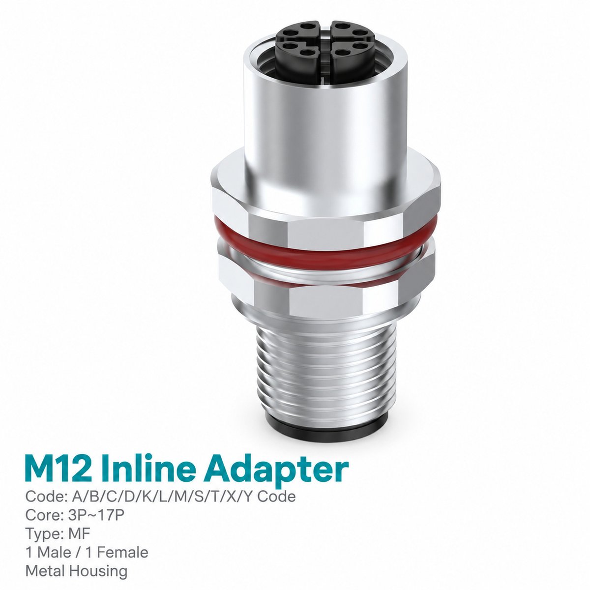
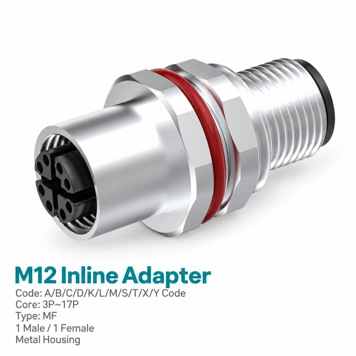
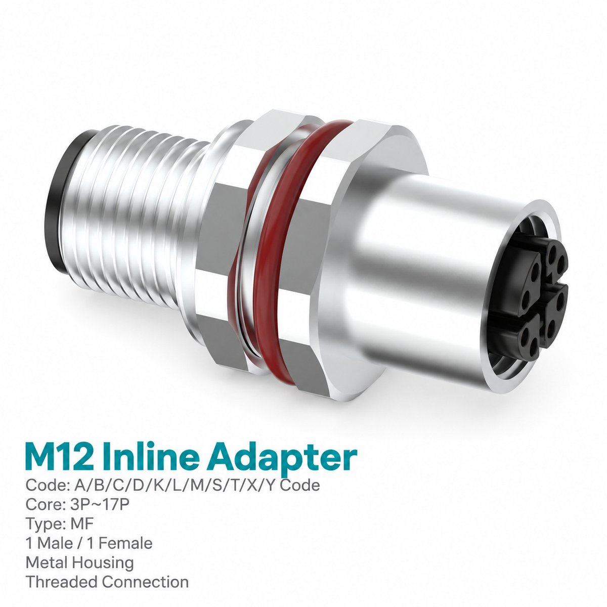
Xmost M12 female-to-male threaded panel adapter provides a shielded connection between compatible M12 interfaces on opposite sides of an equipment panel. One end has a female contact interface, while the other has a male contact interface with an external M12 mating thread.
Its straight I-shaped construction includes an M16 × 1.5 panel mounting thread, mounting nut and sealing ring. The catalog wiring diagrams show corresponding numbered contacts connected pin-to-pin.
This shielded M12 panel feedthrough adapter is available in A-, B-, D- and X-coded configurations. Select the coding, contact count and electrical ratings to match the connected equipment.
Key Features
- Female-to-male M12 interface arrangement.
- Externally threaded male mating interface.
- Shielded panel feedthrough construction.
- M16 × 1.5 panel mounting thread.
- M12 × 1.0 screw-locking connections.
- A-, B-, D- and X-coded options.
- Pin-to-pin wiring as shown in the catalog.
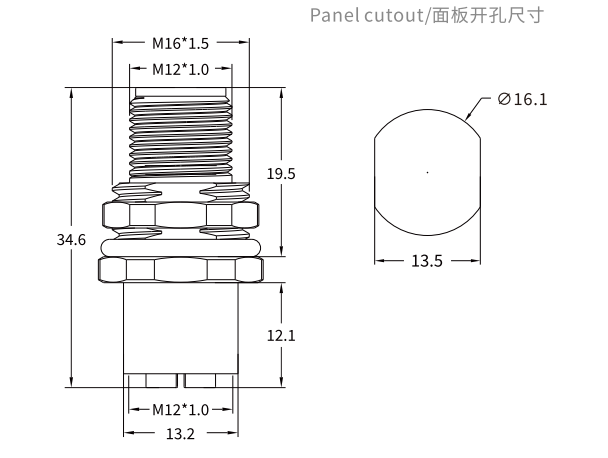
- 34.6 mm axial length in the dimension drawing.
Product Dimensions
Dimensions (mm)
| Dimension | Value |
|---|---|
| Overall axial length shown | 34.6 |
| Upper axial span shown | 19.5 |
| Lower interface span | 12.1 |
| End transverse span shown | 13.2 |
| Panel cutout diameter | Ø16.1 |
| Panel cutout width across flats | 13.5 |
| Panel mounting thread | M16 × 1.5 |
| Mating thread | M12 × 1.0 |
Use the complete panel cutout drawing when preparing the mounting hole.
Needle Arrangement (Front View)

The pin arrangement diagrams show the male and female mating faces viewed from the front. Select the diagram corresponding to the adapter’s coding and contact count.
| Coding | Contact Count |
|---|---|
| A-coded | 3-pin |
| A-coded | 4-pin |
| D-coded | 4-pin |
| A-coded | 5-pin |
| B-coded | 5-pin |
| X-coded | 8-pin |
Read the male and female diagrams in their respective front-view orientations. Use the numbered contacts to identify the matching connections.
Product Specifications
Electrical Ratings by Configuration
| Coding | Contact Count | Rated Current | Rated Voltage |
|---|---|---|---|
| A-coded | 3-pin | 4 A | 250 V |
| A-coded | 4-pin | 4 A | 250 V |
| D-coded | 4-pin | 4 A | 250 V |
| A-coded | 5-pin | 4 A | 60 V |
| B-coded | 5-pin | 4 A | 60 V |
| X-coded | 8-pin | 0.5 A | — |
General Specifications
| Parameter | Specification |
|---|---|
| Brand | Xmost |
| Product Type | I-shape panel-mount adapter |
| Connector Size | M12 |
| Contact Gender | Female / Male |
| Shielding | Shielded |
| Standard Listed in Catalog | IEC 61076-2-101 |
| Panel Mounting Thread | M16 × 1.5 |
| Mating Thread | M12 × 1.0 |
| Internal Contact Connection | Soldering |
| Wiring Arrangement | Corresponding contacts connected pin-to-pin |
| Insulation Resistance | ≥ 100 MΩ |
| Contact Resistance | ≤ 5 mΩ |
| Recommended Tightening Torque | 0.4 N·m |
| Maximum Tightening Torque | 0.8 N·m |
| Dynamic Operating Temperature | −25 °C to +80 °C |
| Static Operating Temperature | −40 °C to +80 °C |
| Protection Ratings Listed | IP67 / IP68 |
| Pollution Degree | 3 |
| Insulator Material Options | PA66 + GF / TPU + GF |
Applications
Suggested applications for this M12 shielded female-to-male panel adapter include:
- Equipment panel connections: A male interface on one side and a female interface on the other.
- Industrial enclosures: Connections between compatible internal wiring and external cable assemblies.
- Automation equipment: Panel interfaces using the selected coding and contact arrangement.
- Fieldbus and network equipment: Connections using matching B-, D- or X-coded interfaces and pin assignments.
Match the connector coding, electrical ratings and shielding arrangement to the equipment.
Wiring Diagram
The catalog diagrams show corresponding numbered contacts connected between the male and female interfaces.
Male Pin 1 connects to Female Pin 1, Male Pin 2 connects to Female Pin 2, and the same numbered connection continues through the remaining contacts of the selected version.
Use the wiring diagram matching the 3-, 4-, 5- or 8-pin adapter.
Selection and Ordering
| Coding | Contact Count | Catalog Part Number |
|---|---|---|
| A-coded | 3-pin | 1M1234AM03MFS |
| A-coded | 4-pin | 1M1234AM04MFS |
| D-coded | 4-pin | 1M1234DM04MFS |
| A-coded | 5-pin | 1M1234AM05MFS |
| B-coded | 5-pin | 1M1234BM05MFS |
| X-coded | 8-pin | 1M1234XM08MFS |
Confirm the contact configuration, panel cutout and mating interfaces before installation.v