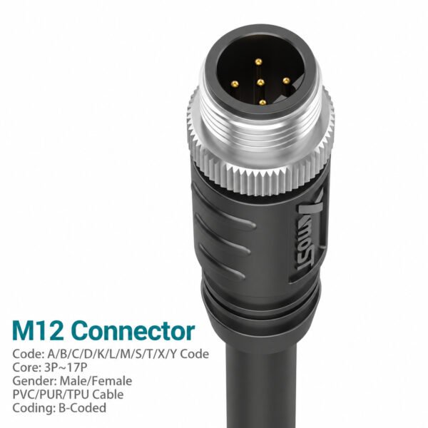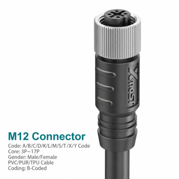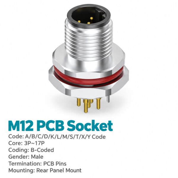
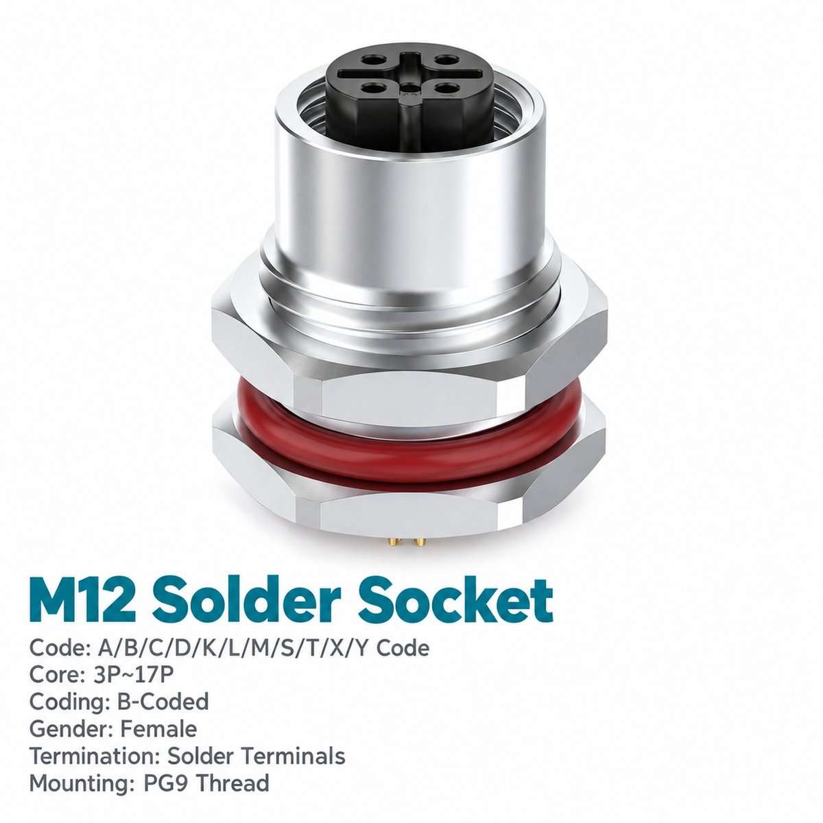
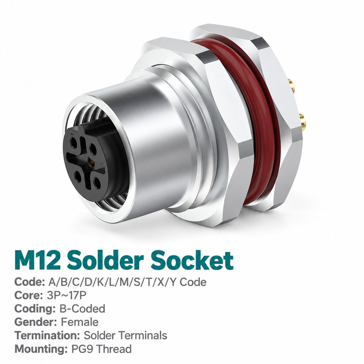
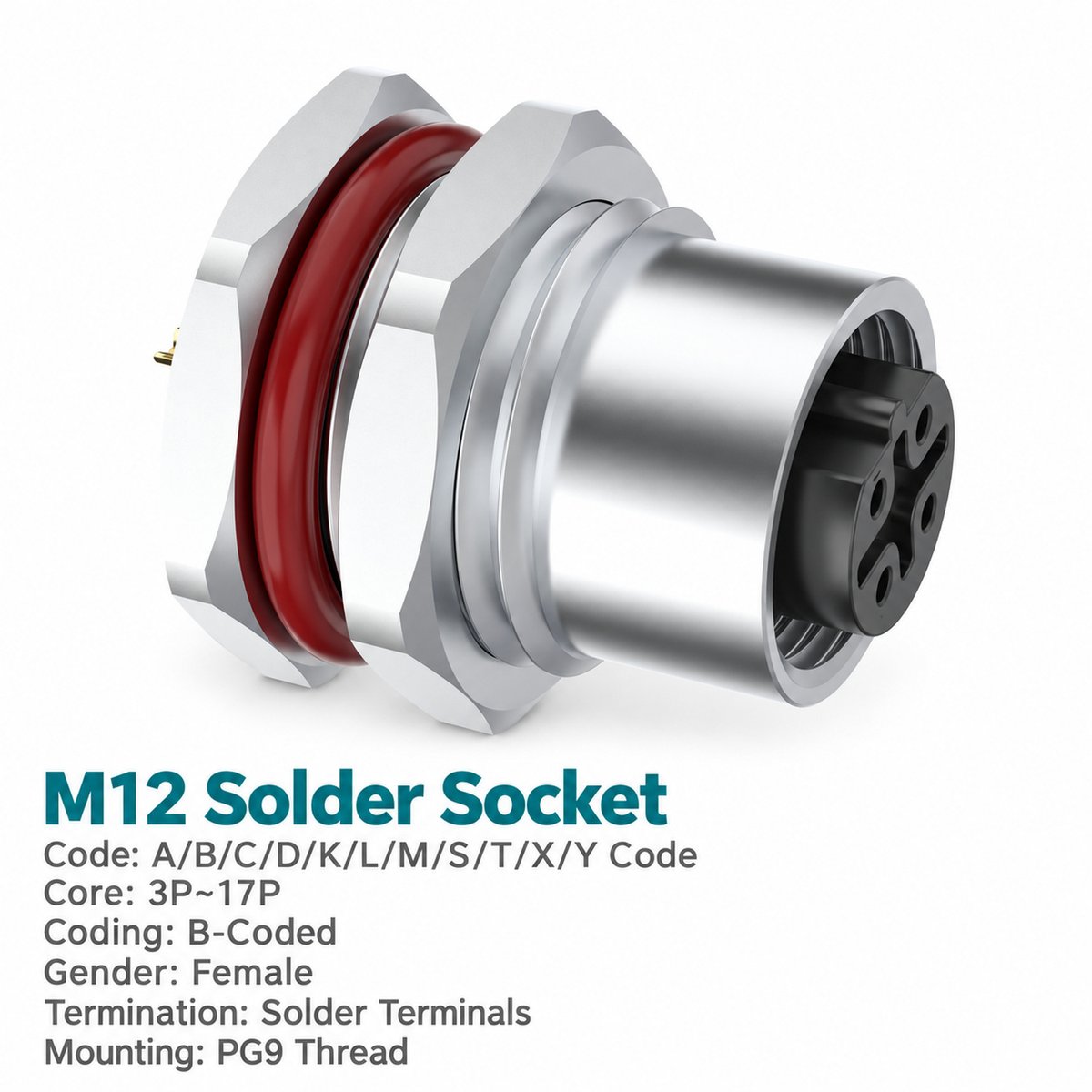
M12 B-coded female front mount socket provides a panel connection for a compatible M12 B-coded male cable connector. The external cable connects at the mating face, while solder terminals or pre-wired leads connect to the internal equipment harness.
Select the front fastened version when it matches the enclosure’s mounting design. The unwired socket allows termination during assembly; pre-wired versions provide 0.1 m, 0.3 m or 0.5 m leads for routing to an internal terminal or circuit connection.
The catalogue identifies the B-coded series for PROFIBUS applications. Confirm that this unshielded version and the complete wiring assembly meet the intended system’s interface and shielding requirements.
Key Features
- 5-pin B-coded female interface: Connects to a compatible M12 B-coded male connector.
- Front fastened mounting: For equipment panels designed around a front mount receptacle.
- Solder termination: Allows wires to be connected during harness assembly.
- Unwired or pre-wired: Choose customer termination or supplied leads.
- Three listed lead lengths: 0.1 m, 0.3 m and 0.5 m.
- PG9 or M16 × 1.5 mounting: Match the mounting thread to the panel opening.
- Rated 4 A / 60 V: Check these ratings against the connected circuits.
- Unshielded construction: As specified for this catalogue version.
Product Dimensions
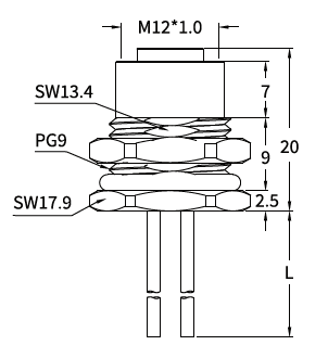
[Insert the front mount female socket drawing and panel cut-out drawing here.]
Illustrated PG9 Version — Dimensions in mm
| Item to Check | Drawing Value |
|---|---|
| Mating thread | M12 × 1.0 |
| Panel mounting thread | PG9 |
| Overall body length shown, excluding leads | 20 |
| Upper axial section shown | 7 |
| Middle axial section shown | 9 |
| Lower axial section shown | 2.5 |
| Upper wrench size | SW13.4 |
| Mounting nut wrench size | SW17.9 |
| Lead length | L; according to ordered version |
The mating thread connects to the cable connector. The panel mounting thread secures the socket to the enclosure. Use the corresponding cut-out drawing for the selected mounting version.
Needle Arrangement (Front View)

[Insert the B-coded 5-pin female contact arrangement screenshot from page 4 here.]
The diagram shows the mating-face view. Follow the female contact numbers when identifying solder terminals and checking the pre-wired lead assignment. Confirm that the external male connector has the matching B-coded arrangement.
Product Specifications
| Parameter | Specification |
|---|---|
| Product type | M12 B-coded female front mount socket |
| Mounting | Front fastened |
| Contact count | 5 pins |
| Termination | Solder |
| Wiring options | Unwired / pre-wired leads |
| Standard listed | IEC 61076-2-101 |
| Rated current | 4 A |
| Rated voltage | 60 V |
| Wire size listed | 0.34 mm² / AWG22 |
| Shielding | Unshielded |
| Coupling thread | M12 × 1.0 |
| Panel mounting thread options | PG9 / M16 × 1.5 |
| Insulation resistance | ≥100 MΩ |
| Contact resistance | ≤5 mΩ |
| Recommended coupling torque | 0.4 N·m |
| Maximum coupling torque | 0.8 N·m |
| Temperature range, flexible use | −25°C to +80°C |
| Temperature range, static use | −40°C to +80°C |
| Protection ratings listed | IP67 / IP68 |
| Pollution degree | 3 |
| Insulator materials listed | PA66+GF / TPU+GF |
Applications
This M12 B-coded front mount female connector can be considered for:
- Industrial equipment panels: Receiving compatible B-coded male cable connections.
- Automation control enclosures: Connecting external cables to internal wiring.
- PROFIBUS-related equipment: Where the complete assembly meets the system requirements.
- Pre-wired machine assemblies: Routing supplied leads to an internal connection point.
Select the connector according to the circuit ratings, wiring assignment and panel design.
Wiring and Lead Options
[Insert the wire colour and pin assignment screenshot from page 4 here.]
| Contact | Wire Colour |
|---|---|
| Pin 1 | Brown — BN |
| Pin 2 | White — WH |
| Pin 3 | Blue — BU |
| Pin 4 | Black — BK |
| Pin 5 | Grey — GY |
The table identifies wire colours by contact number. Assign signal and circuit functions according to the equipment schematic.
Ordering Information
| Wiring Option | PG9 Mounting | M16 × 1.5 Mounting |
|---|---|---|
| Unwired | 1M1207BF05HP9W00 | 1M1207BF05H16W00 |
| 0.1 m leads | 1M1207BF05HP9W10 | 1M1207BF05H16W10 |
| 0.3 m leads | 1M1207BF05HP9W30 | 1M1207BF05H16W30 |
| 0.5 m leads | 1M1207BF05HP9W50 | 1M1207BF05H16W50 |
Example enquiry: M12 B-coded female front mount socket, 5-pin, PG9 mounting, solder termination, 0.3 m pre-wired leads.
Other wire types or lead lengths can be discussed when ordering.