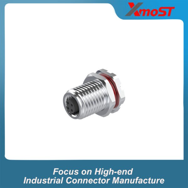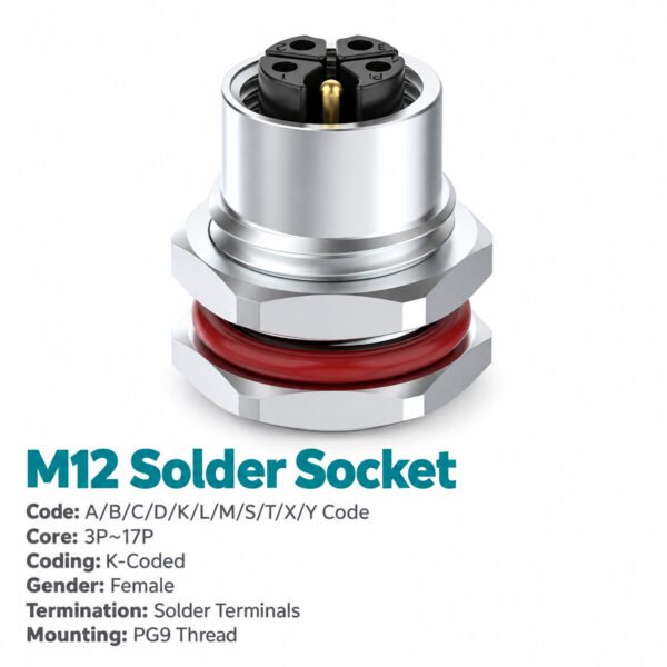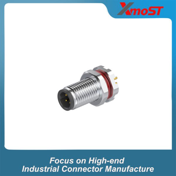
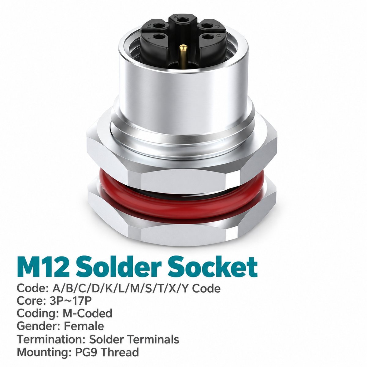
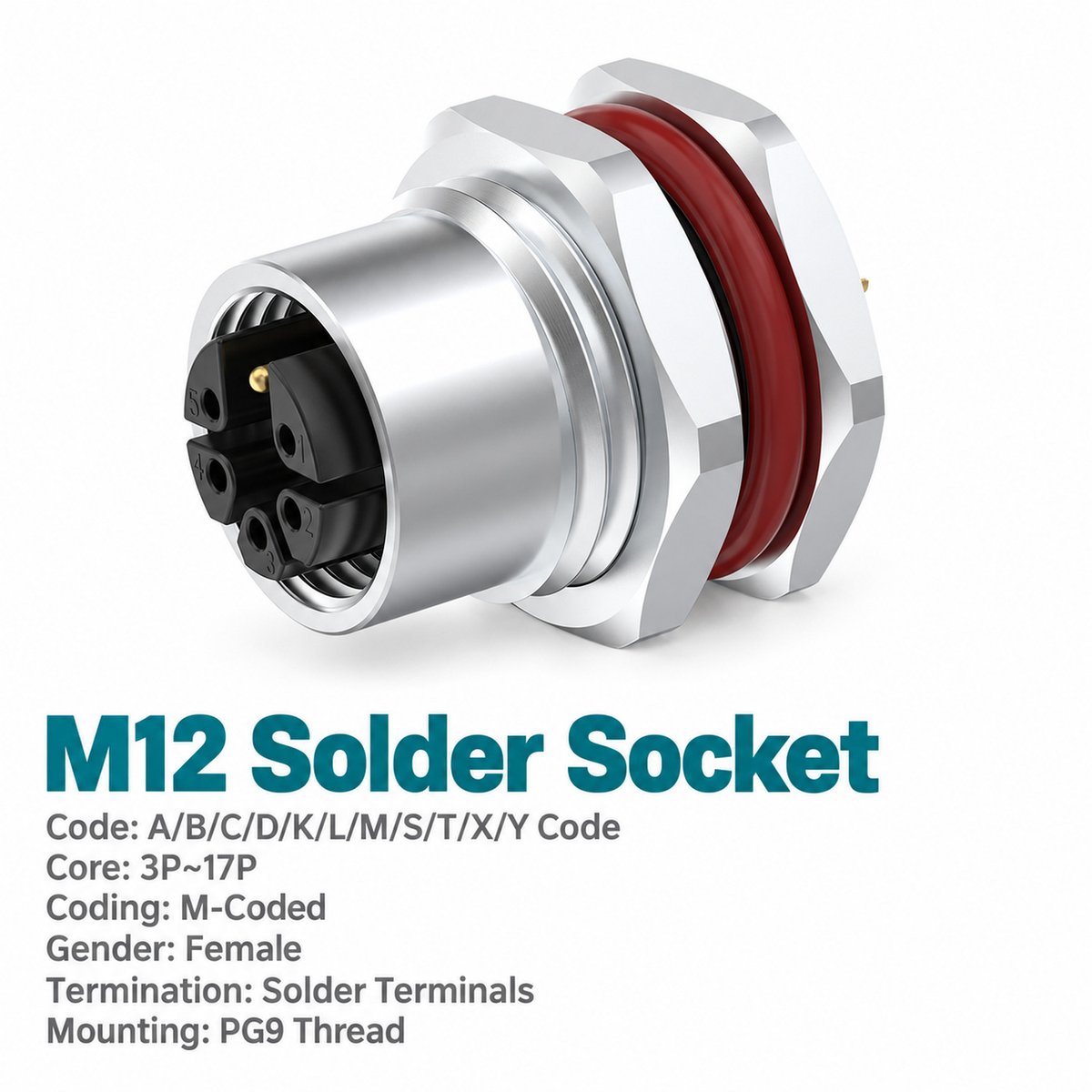
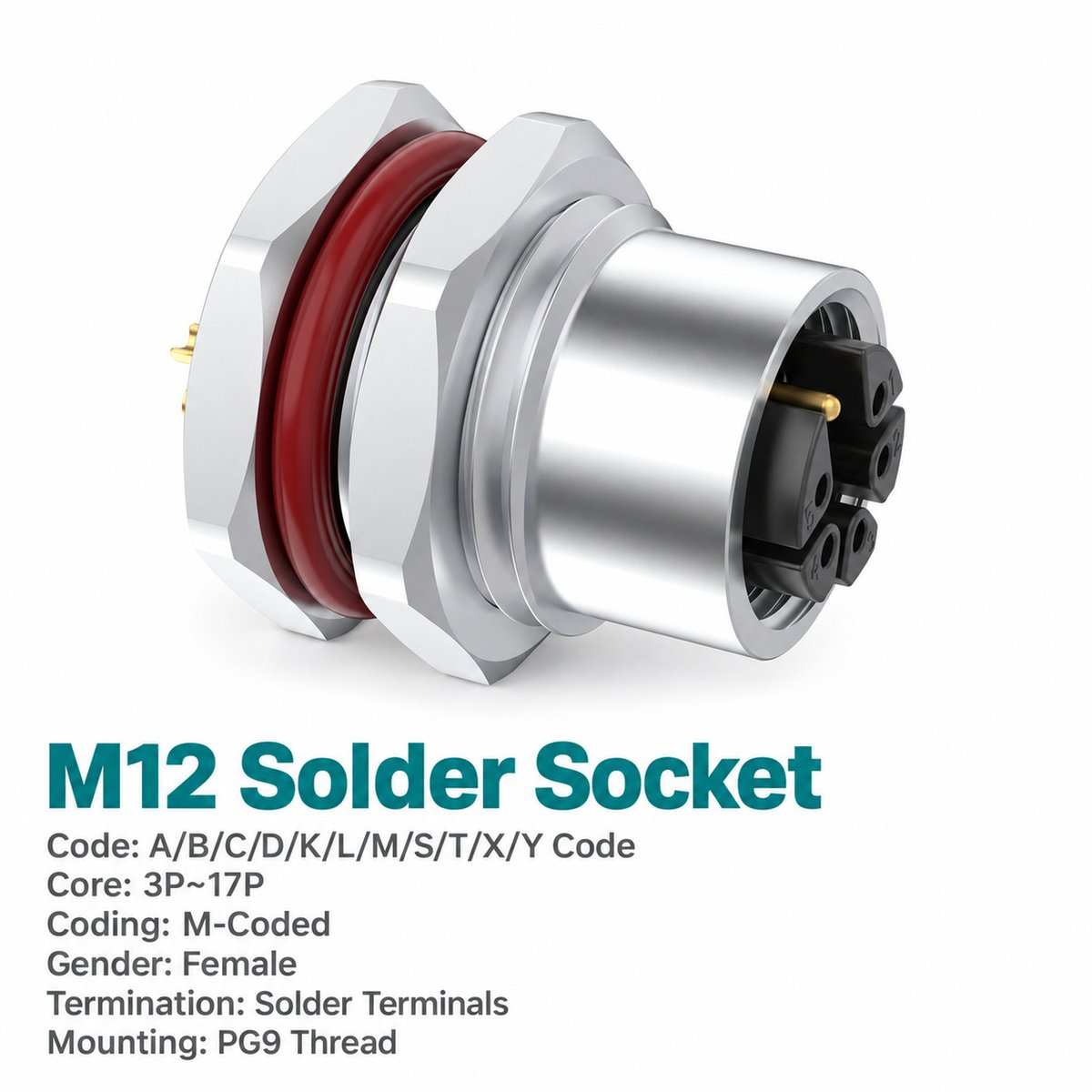
M12 M-coded female front mount socket provides the equipment-side connection for a compatible M12 M-coded male power cable connector. It mounts to the panel, with solder terminals or pre-wired leads connecting to the internal power harness.
Select the front fastened version when it matches the enclosure’s mounting design. The unwired socket allows termination during equipment assembly, while pre-wired versions provide 0.1 m, 0.3 m or 0.5 m leads for routing to an internal terminal or harness connection.
Four contact configurations are available. 4+PE means four circuit contacts plus one protective earth contact, giving five contacts in total. Select the complete contact arrangement according to the equipment schematic and mating connector.
Key Features
- 8 A / 630 V AC power connection: Match these ratings to the equipment circuit.
- M-coded female interface: Connects to a compatible M12 M-coded male connector.
- Front fastened mounting: Select according to the panel installation drawing.
- Solder termination: Supports internal wire connection during assembly.
- Four configurations with PE: Two to five circuit contacts plus protective earth.
- Unwired or pre-wired: Choose customer termination or supplied leads.
- Three listed lead lengths: 0.1 m, 0.3 m and 0.5 m.
- PG9 or M16 × 1.5 mounting: Match the mounting thread to the panel opening.
Product Dimensions
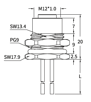
[Insert the front mount female socket drawing and panel cut-out drawing here.]
Illustrated PG9 Version — Dimensions in mm
| Item to Check | Drawing Value |
|---|---|
| Mating thread | M12 × 1.0 |
| Panel mounting thread | PG9 |
| Overall body length shown, excluding leads | 20 |
| Upper axial section shown | 7 |
| Middle axial section shown | 9 |
| Lower axial section shown | 2.5 |
| Upper wrench size | SW13.4 |
| Mounting nut wrench size | SW17.9 |
| Lead length | L; according to ordered version |
The mating thread connects to the external cable connector. The panel mounting thread secures the socket to the enclosure. Use the corresponding cut-out drawing for the selected mounting version.
Needle Arrangement (Front View)

[Insert the M-coded female contact arrangement screenshot from page 21 after checking the PE labels.]
| Configuration | Circuit Contacts | PE Contact | Total Contacts | Circuit Positions Used |
|---|---|---|---|---|
| 2+PE | 2 | 1 | 3 | 2, 4 |
| 3+PE | 3 | 1 | 4 | 1, 3, 5 |
| 4+PE | 4 | 1 | 5 | 1, 2, 4, 5 |
| 5+PE | 5 | 1 | 6 | 1, 2, 3, 4, 5 |
The diagrams show the mating-face view. Contact positions are not consecutively populated in every version. For example, the 3+PE version uses circuit positions 1, 3 and 5, together with PE.
Product Specifications
| Parameter | Specification |
|---|---|
| Product type | M12 M-coded female front mount AC power socket |
| Mounting | Front fastened |
| Termination | Solder |
| Wiring options | Unwired / pre-wired leads |
| Standard listed | IEC 61076-2-111 |
| Rated current | 8 A |
| Rated voltage | 630 V |
| Wire size listed | 1.5 mm² / AWG16 |
| Shielding | Unshielded |
| Coupling thread | M12 × 1.0 |
| Panel mounting thread options | PG9 / M16 × 1.5 |
| Insulation resistance | ≥100 MΩ |
| Contact resistance | ≤5 mΩ |
| Recommended coupling torque | 0.4 N·m |
| Maximum coupling torque | 0.8 N·m |
| Temperature range, flexible use | −25°C to +80°C |
| Temperature range, static use | −40°C to +80°C |
| Protection ratings listed | IP67 / IP68 |
| Pollution degree | 3 |
| Insulator materials listed | PA66+GF / TPU+GF |
Applications
This M12 M-coded front mount female power connector can be considered for:
- Machine power panels: Connecting an external AC cable to internal equipment wiring.
- Industrial control enclosures: Providing a detachable power interface with protective earth.
- Modular equipment: Allowing the external power cable to disconnect at the housing.
- Pre-wired machine assemblies: Routing supplied leads to an internal connection point.
Select the configuration according to the circuit ratings, required conductor count and panel design.
Wiring and Lead Options
[Insert the wire colour and pin assignment screenshot from page 21 here.]
| Contact Position | 2+PE | 3+PE | 4+PE | 5+PE |
|---|---|---|---|---|
| Pin 1 | — | Black 1 — BK1 | Black 1 — BK1 | Black 1 — BK1 |
| Pin 2 | Black 2 — BK2 | — | Black 2 — BK2 | Black 2 — BK2 |
| Pin 3 | — | Black 3 — BK3 | — | Black 3 — BK3 |
| Pin 4 | Black 4 — BK4 | — | Black 4 — BK4 | Black 4 — BK4 |
| Pin 5 | — | Black 5 — BK5 | Black 5 — BK5 | Black 5 — BK5 |
| Pin 6 / PE | Yellow/green — YE/GN | Yellow/green — YE/GN | Yellow/green — YE/GN | Yellow/green — YE/GN |
“—” means the position is not used. Assign circuit functions to the numbered black conductors according to the equipment schematic. The yellow/green conductor is the protective earth lead.
Selection and Ordering
| Selection Item | Available Choices |
|---|---|
| Contact arrangement | 2+PE / 3+PE / 4+PE / 5+PE |
| Mounting style | Front mount |
| Panel mounting thread | PG9 / M16 × 1.5 |
| Termination | Solder |
| Wiring | Unwired / pre-wired |
| Listed lead lengths | 0.1 m / 0.3 m / 0.5 m |
| Custom requirements | Specify wire type or lead length |
Example enquiry: M12 M-coded female front mount socket, 4+PE, PG9 mounting, solder termination, 0.3 m pre-wired leads.