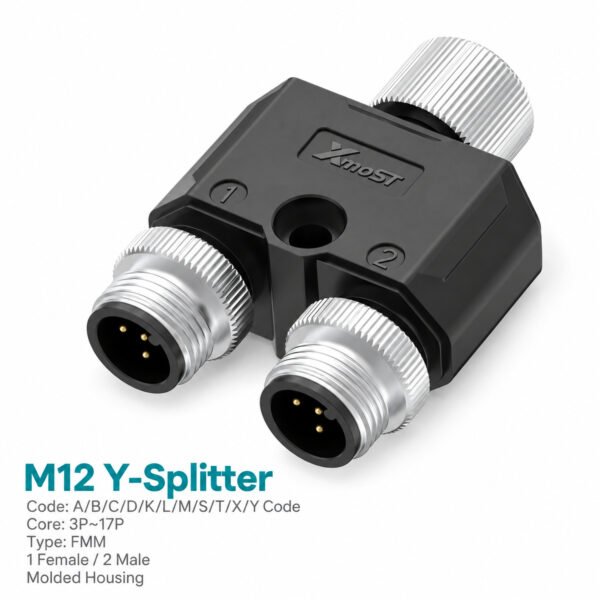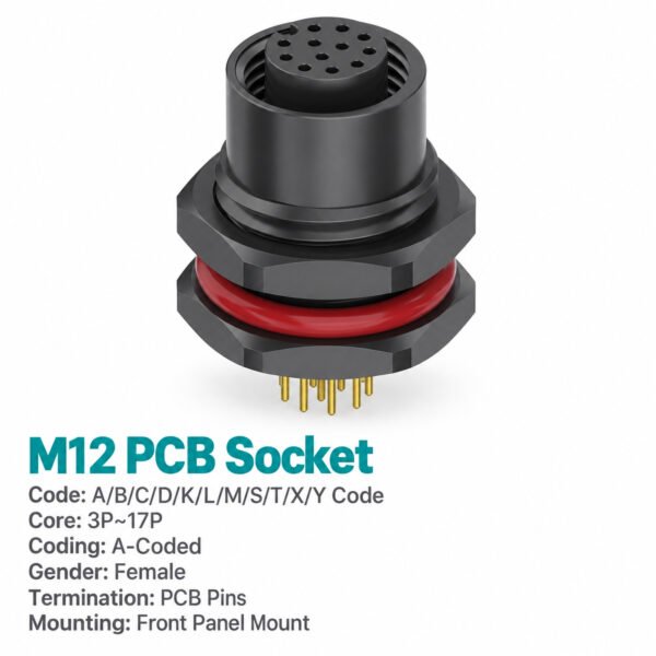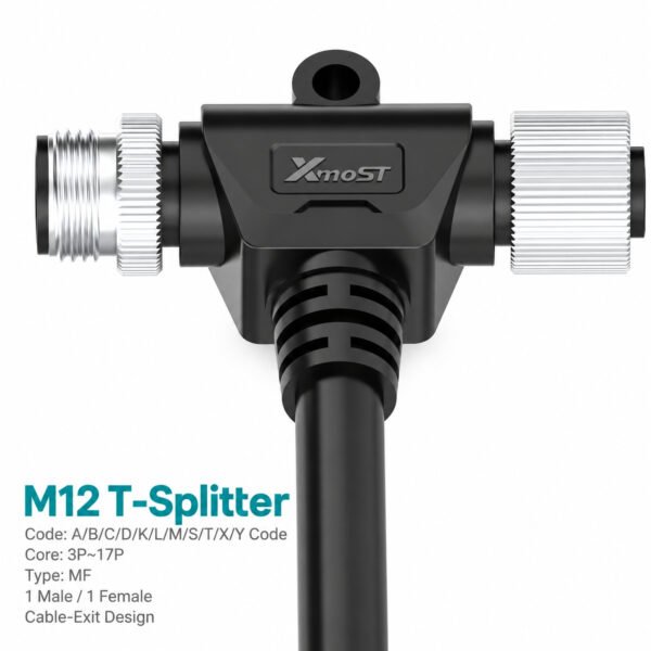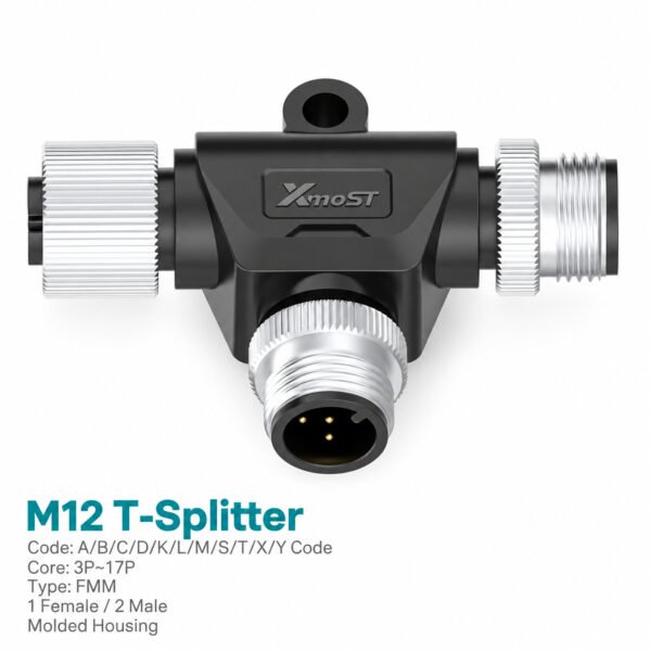
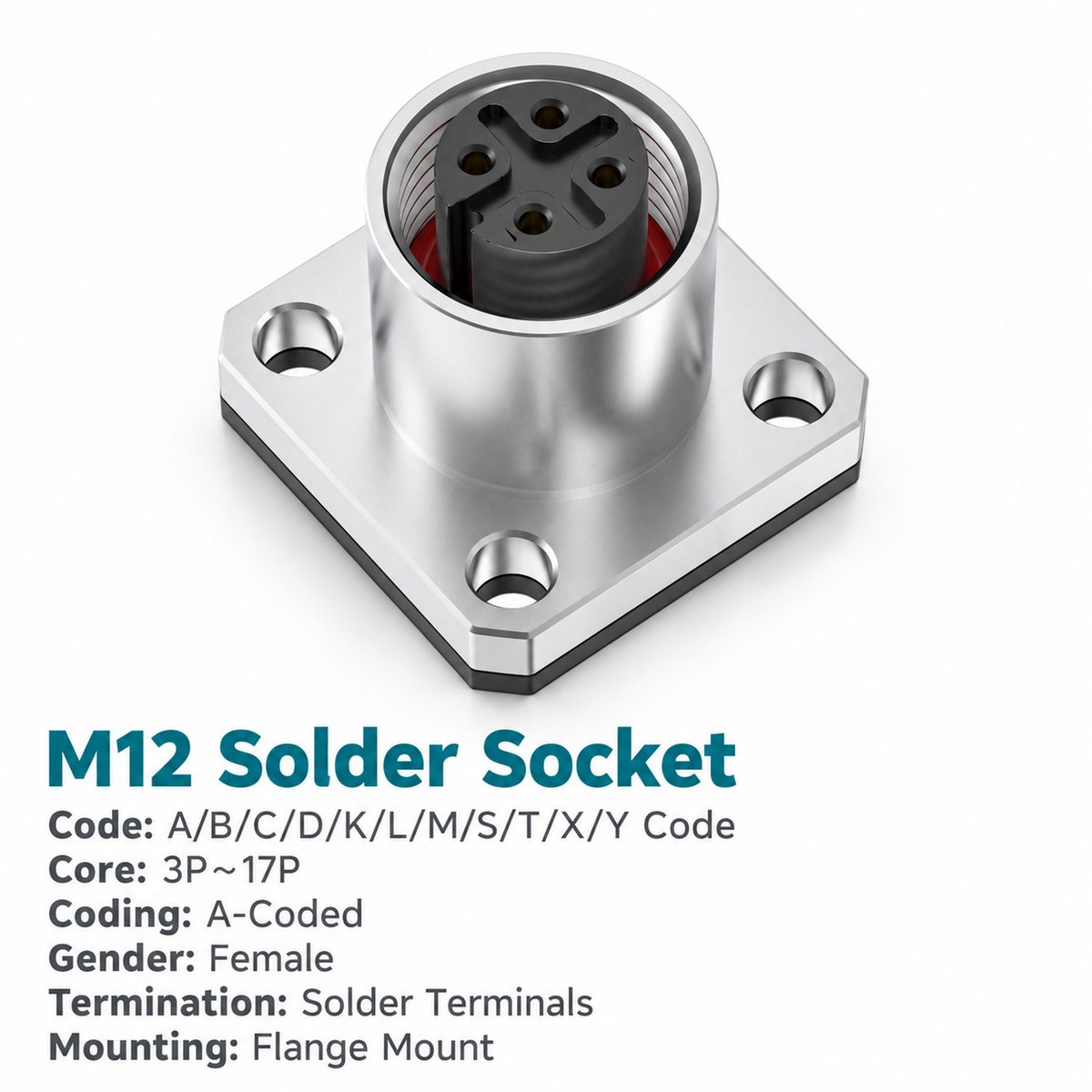
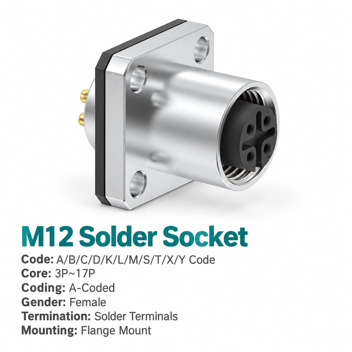
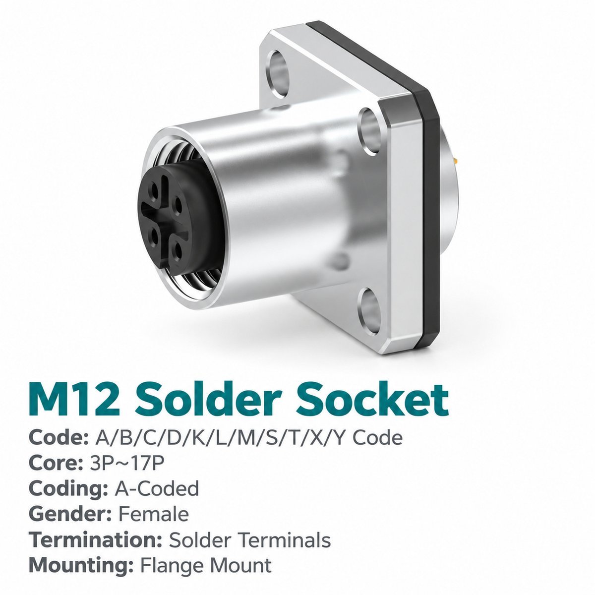
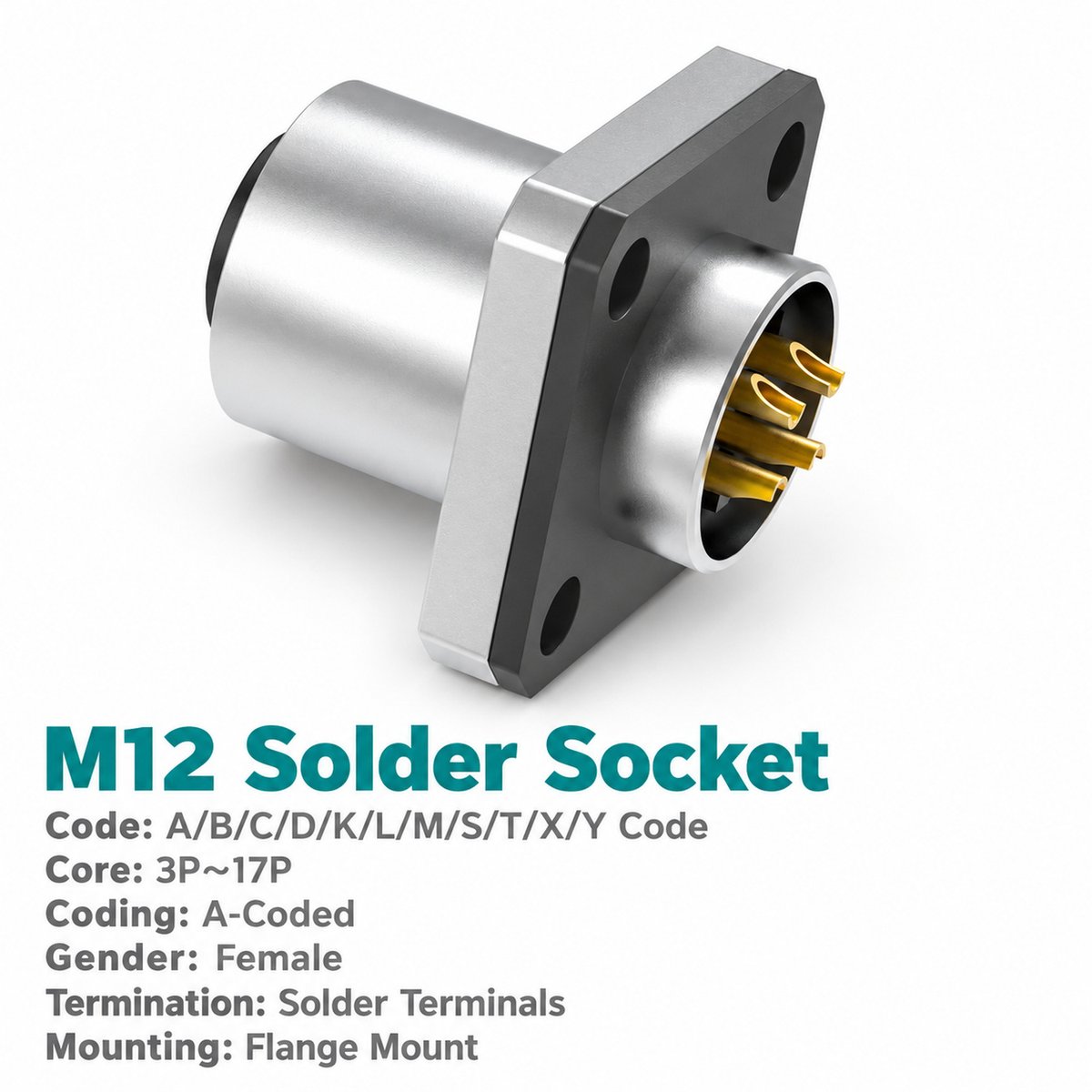
Xmost M12 A-coded female flange socket creates a panel interface for a compatible M12 A-coded male cable connector. Four mounting holes secure the square flange to the equipment housing, with the wiring connection located behind the panel.
Choose an unwired M12 female solder socket for termination during assembly or a pre-wired version for connection to the equipment harness. The available contact counts allow the interface to be matched to the number and ratings of the required circuits.
Key Features
- Female mating interface: Connects to a compatible M12 A-coded male connector.
- Square flange mounting: Four fixing holes for attachment to the equipment panel.
- Solder connection: Supports internal wire termination.
- Wiring choices: Unwired or supplied with the listed 0.3 m leads.
- 3–17 pin options: Six configurations for different circuit requirements.
- M12 threaded coupling: M12 × 1.0 mating connection.
- Unshielded design: For applications that do not require connector shielding.
Product Dimensions
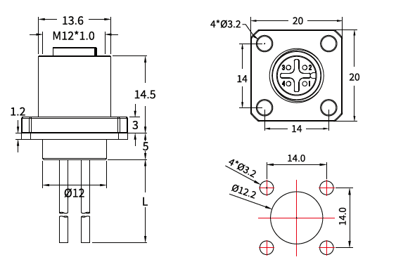
[Insert the female flange socket dimension drawing and panel cut-out drawing here.]
| Dimension Item | Value |
|---|---|
| Coupling thread | M12 × 1.0 |
| Upper body diameter shown | Ø13.6 |
| Flange size | 20 × 20 |
| Fixing-hole centre spacing | 14 × 14 |
| Flange fixing holes | 4 × Ø3.2 |
| Recommended panel fixing holes | 4 × Ø3.2 |
| Recommended panel centre opening | Ø12.2 |
| Upper axial dimension shown | 14.5 |
| Flange thickness shown | 3 |
| Lower axial dimension shown | 5 |
| Rear body diameter shown | Ø12 |
| Additional dimension shown | 1.2; refer to drawing |
| Lead length | L, according to ordered version |
| Unit | mm |
Needle Arrangement (Front View)

[Insert only the female needle arrangement row from page 26: 3, 4, 5, 8, 12 and 17 pins.]
The female contact positions are shown from the mating face. Refer to this female arrangement when identifying terminals and checking the connection to a mating male connector.
Product Specifications
| Parameter | Specification |
|---|---|
| Brand | Xmost |
| Connector type | M12 A-coded female flange socket |
| Mounting | Four-hole flange |
| Termination | Solder |
| Wiring options | Unwired / pre-wired |
| Standard listed | IEC 61076-2-101 |
| Shielding | Unshielded |
| Coupling thread | M12 × 1.0 |
| Insulation resistance | ≥100 MΩ |
| Contact resistance | ≤5 mΩ |
| Recommended coupling torque | 0.4 N·m |
| Maximum coupling torque | 0.8 N·m |
| Temperature range, flexible use | −25°C to +80°C |
| Temperature range, static use | −40°C to +80°C |
| Protection ratings listed | IP67 / IP68 |
| Pollution degree | 3 |
| Insulator materials listed | PA66+GF / TPU+GF |
Electrical Ratings
| Contact Count | Rated Current | Rated Voltage | Wire Size Listed |
|---|---|---|---|
| 3 pins | 4 A | 250 V | 0.34 mm² / AWG22 |
| 4 pins | 4 A | 250 V | 0.34 mm² / AWG22 |
| 5 pins | 4 A | 60 V | 0.34 mm² / AWG22 |
| 8 pins | 4 A | 30 V | 0.25 mm² / AWG24 |
| 12 pins | 1.5 A | 30 V | 0.14 mm² / AWG26 |
| 17 pins | 1.5 A | 30 V | 0.14 mm² / AWG26 |
Applications
This M12 A-coded female panel mount connector can be selected for:
- Equipment panels receiving M12 male cable connections.
- Sensor and actuator connection points on automated machinery.
- Control housings with internal soldered wire harnesses.
- Industrial assemblies requiring four-hole flange mounting.
- Multi-contact signal interfaces between external cables and internal circuits.
Check the selected configuration against the required current, voltage and available panel space.
Wiring and Lead Options
[Insert the wire colour and pin assignment table from page 26 here.]
The female flange socket is offered without wires or with 0.3 m pre-wired leads. Specify the contact count and wiring option when selecting the part number. Other lead lengths and cable types can be discussed for the application.
The 3-pin version uses pins 1, 3 and 4. Follow the female front-view arrangement together with the matching wire assignment table.
Ordering Information
| Contacts | Unwired Part Number | 0.3 m Pre-Wired Part Number |
|---|---|---|
| 3 pins | 1M1209AF03H12W00 | 1M1209AF03H12W30 |
| 4 pins | 1M1209AF04H12W00 | 1M1209AF04H12W30 |
| 5 pins | 1M1209AF05H12W00 | 1M1209AF05H12W30 |
| 8 pins | 1M1209AF08H12W00 | 1M1209AF08H12W30 |
| 12 pins | 1M1209AF12H12W00 | 1M1209AF12H12W30 |
| 17 pins | 1M1209AF17H12W00 | 1M1209AF17H12W30 |