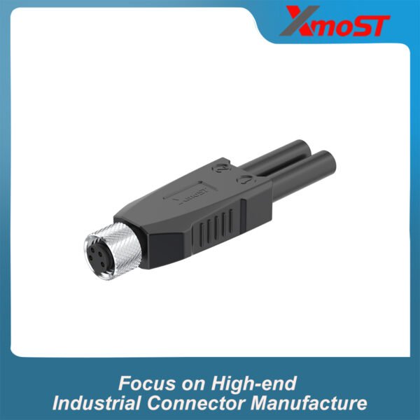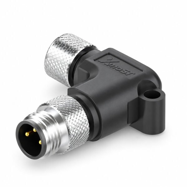
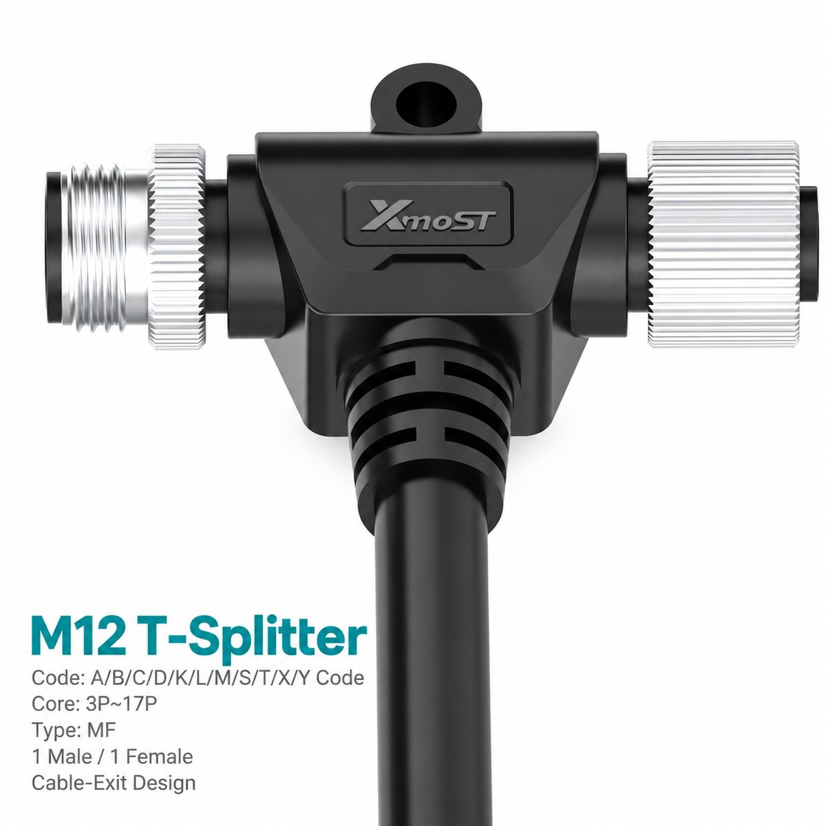
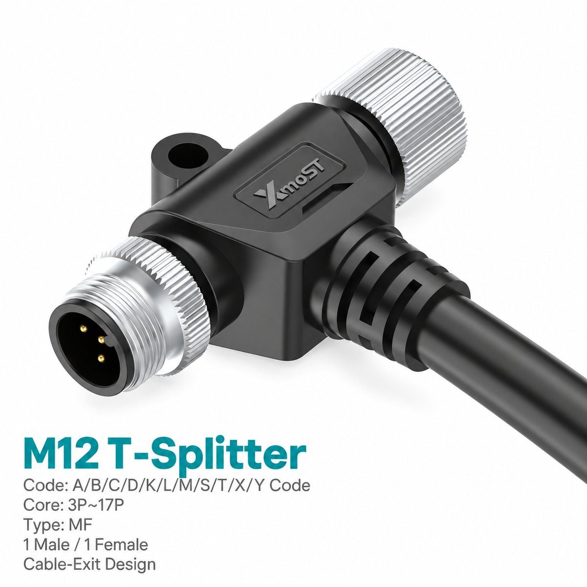
Xmost M12 T-shape splitter with cable branch provides an inline male-to-female connection and an integrated cable connection in one molded housing. The male and female interfaces sit along the same axis, while the cable exits through the lower branch.
The catalog wiring diagrams show corresponding numbered contacts connected in parallel between the male interface, female interface and cable conductors. This M12 cable splitter therefore provides access to the shared circuits through the attached cable.
Both connector interfaces use M12 × 1.0 screw locking. An integrated mounting eye provides a fixing point for securing the adapter to equipment.
A- and B-coded versions are unshielded, while the D-coded version is shielded. PVC and PUR cable options are listed in 1 m, 3 m and 5 m lengths.
Key Features
- One male and one female M12 interface with an integrated cable branch.
- Compact T-shaped molded housing.
- Parallel pin-to-pin wiring between the connector interfaces and cable conductors.
- A-, B- and D-coded options.
- 3-, 4-, 5- and 8-pin configurations, depending on coding.
- M12 × 1.0 screw-locking connections.
- Integrated mounting eye with a Ø4.2 mm hole.
- PVC or PUR cable options in 1 m, 3 m and 5 m lengths.
- Unshielded A-/B-coded versions and a shielded D-coded version.
Product Dimensions
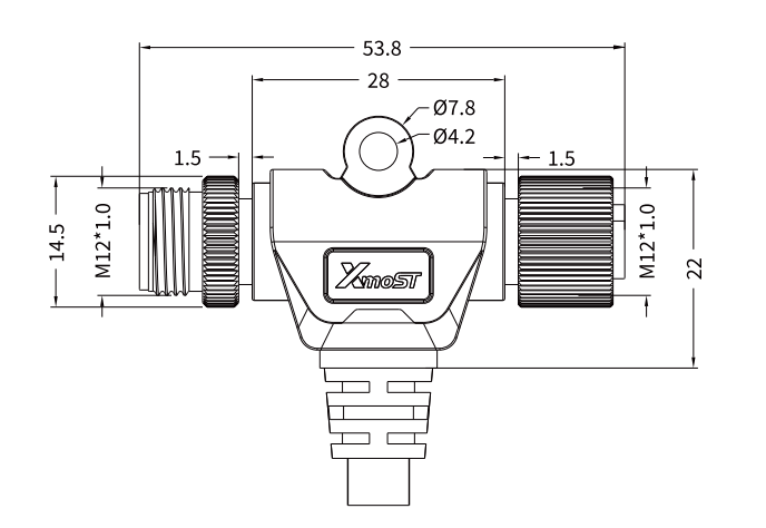
Dimensions (mm)
| Dimension | Value |
|---|---|
| Overall horizontal span shown | 53.8 |
| Upper body horizontal span shown | 28 |
| Body vertical span shown | 22 |
| Coupling diameter | Ø14.5 |
| Mounting hole diameter | Ø4.2 |
| Mounting eye outside diameter | Ø7.8 |
| Interface spacing marked | 1.5 |
| Mating thread | M12 × 1.0 |
Dimensions correspond to the marked spans in the catalog drawing. The 22 mm span does not include the full cable-exit section. Cable length is specified separately.
Needle Arrangement (Front View)

The pin arrangement diagrams show the male and female mating faces viewed from the front. Select the diagram matching the splitter’s coding and contact count.
| Coding | Contact Count |
|---|---|
| A-coded | 3-pin |
| A-coded | 4-pin |
| D-coded | 4-pin |
| A-coded | 5-pin |
| B-coded | 5-pin |
| A-coded | 8-pin |
Read the male and female diagrams in their respective orientations. Use the numbered contacts and key position to identify each connection.
Product Specifications
Electrical Ratings by Configuration
| Coding | Contact Count | Rated Current | Rated Voltage | Shielding |
|---|---|---|---|---|
| A-coded | 3-pin | 4 A | 250 V | Unshielded |
| A-coded | 4-pin | 4 A | 250 V | Unshielded |
| D-coded | 4-pin | 4 A | 250 V | Shielded |
| A-coded | 5-pin | 4 A | 60 V | Unshielded |
| B-coded | 5-pin | 4 A | 60 V | Unshielded |
| A-coded | 8-pin | 2 A | 30 V | Unshielded |
General Specifications
| Parameter | Specification |
|---|---|
| Brand | Xmost |
| Connector Size | M12 |
| Product Type | T-shape splitter with cable branch |
| Interface Type | Male / Female |
| Cable Connection | Integrated branch cable |
| Standard Listed | IEC 61076-2-101 |
| Locking Method | M12 × 1.0 screw locking |
| Wiring Arrangement | Corresponding contacts and cable conductors connected in parallel |
| Wire Size Listed | 0.34 mm² / AWG22 |
| Insulation Resistance | ≥ 100 MΩ |
| Contact Resistance | ≤ 5 mΩ |
| Recommended Tightening Torque | 0.4 N·m |
| Maximum Tightening Torque | 0.8 N·m |
| Dynamic Operating Temperature | −25 °C to +80 °C |
| Static Operating Temperature | −40 °C to +80 °C |
| Protection Ratings Listed | IP67 / IP68 |
| Pollution Degree | 3 |
| Insulator Material Options | PA66 + GF / TPU + GF |
Applications
Suggested applications for this M12 male-to-female cable splitter include:
- Machine wiring junctions: Inline M12 connections requiring access to shared circuits through a cable branch.
- Compatible field-device wiring: Connections using the selected coding and contact arrangement.
- Automation equipment: Cable branches to compatible terminal or equipment connections.
- Secured cable installations: Junctions where the mounting eye can hold the splitter in position.
Use the splitter where the equipment supports the illustrated parallel wiring. Check the combined load carried by shared contacts. For communication circuits, confirm that the network permits the branch topology.
Wiring Diagram
The catalog diagrams show each numbered male contact connected to the corresponding female contact and cable conductor.
For example:
- Male Pin 1 connects to Female Pin 1 and cable conductor 1.
- Male Pin 2 connects to Female Pin 2 and cable conductor 2.
- The same numbered connection continues through the remaining contacts.
The cable branch shares the connector circuits; it is not an independently switched channel. Use the wiring diagram matching the 3-, 4-, 5- or 8-pin version, and confirm conductor identification before wiring.
Selection and Ordering
Select the coding, contact count, cable jacket and cable length.
| Selection Item | Available Options |
|---|---|
| A-coded Contact Configurations | 3-pin / 4-pin / 5-pin / 8-pin |
| B-coded Contact Configuration | 5-pin |
| D-coded Contact Configuration | 4-pin |
| Cable Jacket | PVC / PUR |
| Cable Length | 1 m / 3 m / 5 m |
Example Part Numbers — 1 m Cable
| Coding | Contact Count | PVC Cable | PUR Cable |
|---|---|---|---|
| A-coded | 3-pin | 1M1232AH03MF1100 | 1M1232AH03MF2100 |
| A-coded | 4-pin | 1M1232AH04MF1100 | 1M1232AH04MF2100 |
| D-coded | 4-pin | 1M1232DH04MF1100S | 1M1232DH04MF2100S |
| A-coded | 5-pin | 1M1232AH05MF1100 | 1M1232AH05MF2100 |
| B-coded | 5-pin | 1M1232BH05MF1100 | 1M1232BH05MF2100 |
| A-coded | 8-pin | 1M1232AH08MF1100 | 1M1232AH08MF2100 |
For 3 m and 5 m versions, select the corresponding part number from the catalog ordering table. Confirm the parallel wiring, electrical requirements and installation clearance before ordering.