M12 circular connectors are the industry standard for factory automation, sensor networks, fieldbus systems, and industrial Ethernet applications. The front-lock panel-mount receptacle (available with male pins or female sockets) provides a reliable, vibration-resistant, and IP67-rated solution for equipment requiring quick disconnect and secure sealing.
This tutorial walks you through the complete installation process of an M12 front-lock male/female pin socket, from component preparation to final soldering. All steps are accompanied by practical GIFs for easy reference.
What You Will Learn
- Component layout and identification for M12 front-lock connectors
- Panel insertion and front-lock nut tightening from the interior side
- Pin orientation, insertion, and soldering technique for field termination
- Key industry terms: overmolded, field-wireable, A-coded / B-coded / D-coded, IP67 sealing
Tools & Materials Required
| Item | Specification |
|---|---|
| M12 front-lock receptacle | Male pin or female socket type |
| Front-lock nut | Included with connector |
| Sealing O-ring | Included |
| Mounting panel | Thickness 1–4 mm, 12–12.1 mm cutout |
| Torque wrench | 0.6 N·m recommended |
| Soldering station | For field-wireable termination |
| Wire stripper | AWG 24–18 |
Component Preparation & Layout

What the GIF shows:
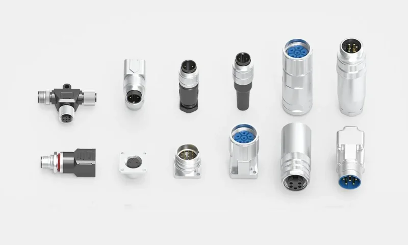
All M12 front-lock connector components are placed on a clean, ESD-safe work surface. The image clearly identifies:
- Connector housing – threaded body with front-lock flange
- Front-lock nut – serrated or hex-shaped for hand or tool tightening
- Sealing O-ring – provides IP67 ingress protection when compressed against the panel
- Male pins (pins) – for receptacle side that receives a female cable plug
- Female sockets (sockets) – for receptacle side that receives a male cable plug
Panel Insertion & Hand Tightening of Front-Lock Nut
What the GIF shows:
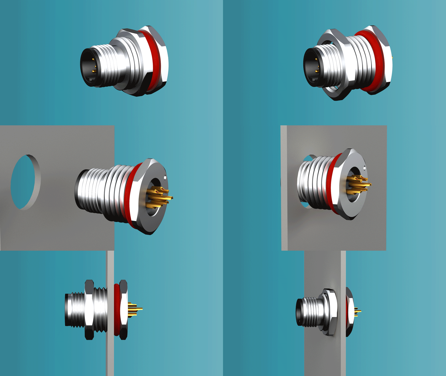
The M12 front-lock receptacle is inserted from the outside of the equipment panel (exterior side). The threaded section passes through the 12 mm panel cutout and protrudes into the interior side (inside the junction box or control cabinet). Then, the front-lock nut is hand-tightened onto the threads from the interior.
Critical distinction – front-lock vs. rear-lock:
- Front-lock (this guide): Nut is tightened from inside the panel. The connector body is inserted from outside. Ideal for pre-assembled panels where exterior access is limited.
- Rear-lock: Nut is tightened from outside. Different mechanical sequence.
Pin Orientation, Insertion & Soldering
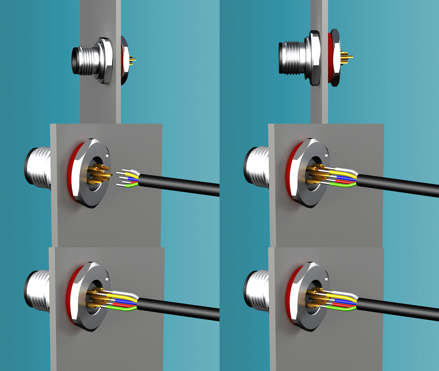
What the GIF shows:
After the front-lock nut is hand-secured, the installer guides the male pins or female sockets into their respective cavities according to the M12 coding diagram. The pins are then soldered to individual wires (or crimped, depending on connector type).
- Orientation guide: Pin 1 position marked on housing
- Insertion depth: Pins click fully into the insulator
- Soldering technique: Heat applied to the cup, not directly to the wire insulation
- Strain relief: Optional overmolding or heat shrink tubing for cable exit
When terminating a field-wireable M12 connector, proper soldering of male pins (for a male pin socket receptacle) or female sockets (for a female socket receptacle) ensures signal integrity in PROFINET, DeviceNet, and Ethernet/IP networks. Always verify the coding before soldering:
- A-coded – most common for sensors, actuators, and analog signals
- B-coded – PROFIBUS and fieldbus applications
- D-coded – 100 Mbps industrial Ethernet
- X-coded – 10 GbE high-speed vision systems
For sensor-actuator interface (SAI) applications, the M12 circular connector serves as a reliable panel feed-through connector, allowing quick disconnect without opening the enclosure.