
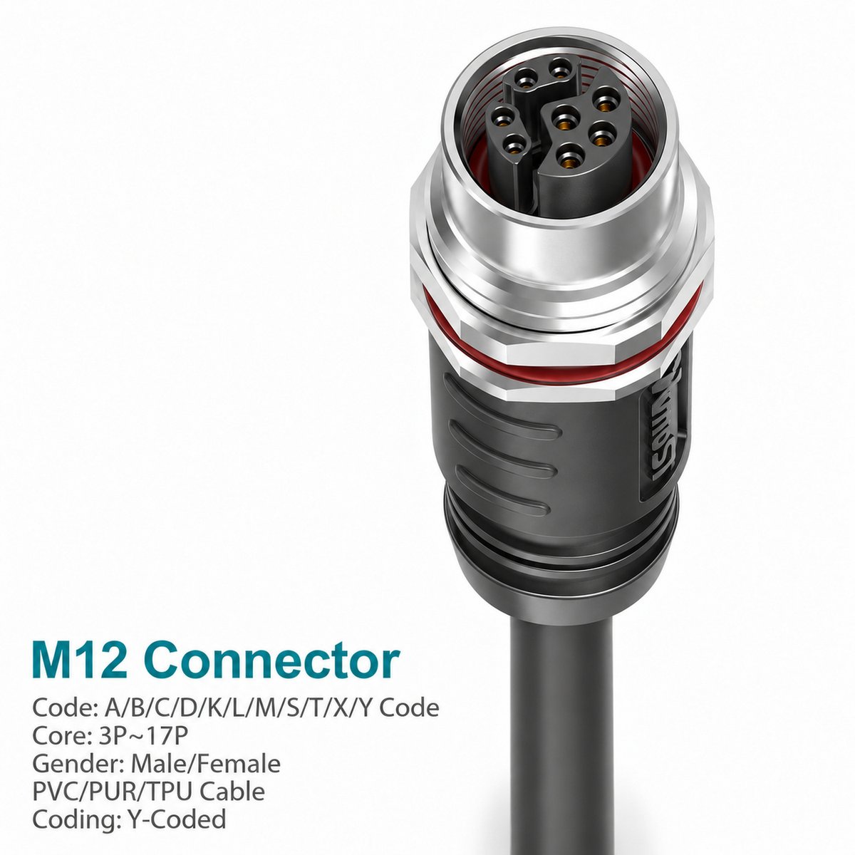
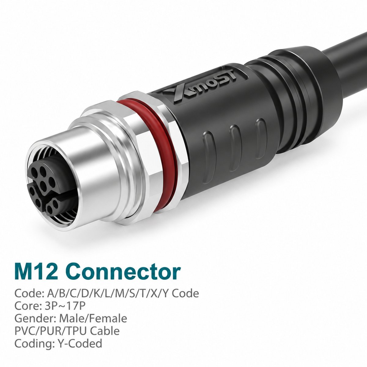
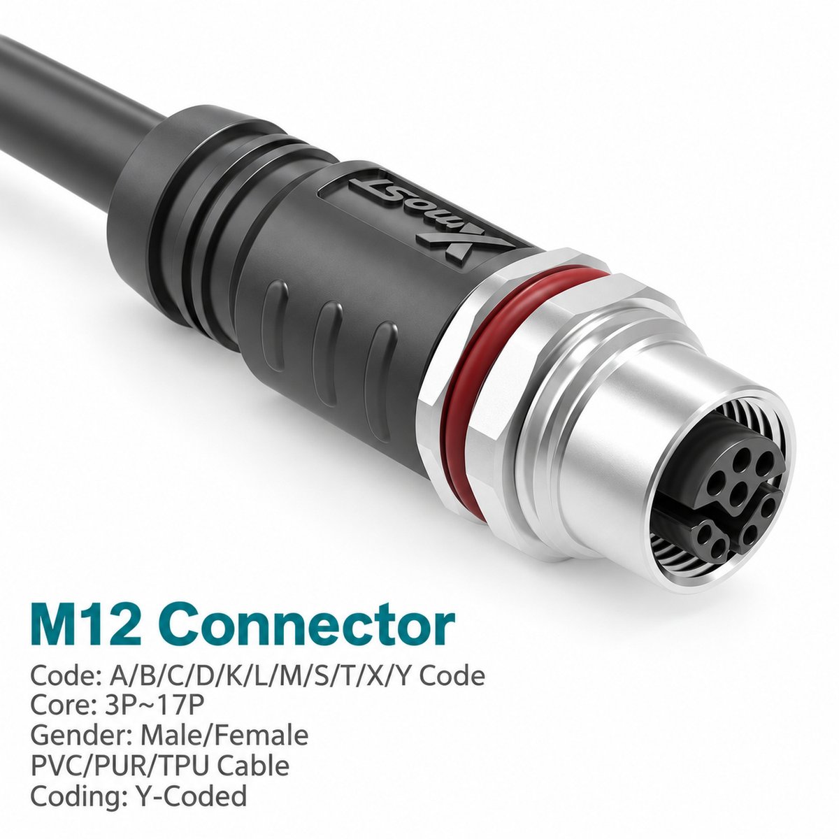
Xmost M12 Y-coded female panel-mount CAT5e connector provides a shielded equipment interface with an integrated single-ended cable. Its straight panel-mount construction brings the connection through an equipment wall or enclosure panel.
This M12 hybrid Ethernet cable assembly combines four signal contacts with either two or four power contacts. The catalog identifies CAT5e, 100 Mbps Ethernet applications and specifies separate current ratings for the power and signal circuits.
The female interface mates with a matching Y-coded male connector using M12 × 1.0 screw locking. PG9 and M16 × 1.5 mounting options are listed, with PVC or PUR cable in 1 m, 3 m and 5 m lengths.
Key Features
- M12 Y-coded female interface combining power and signal contacts.
- Shielded CAT5e cable assembly for the catalog-listed 100 Mbps Ethernet application.
- Straight panel-mount construction.
- 4 signal + 2 power or 4 signal + 4 power configurations.
- 50 V rated voltage.
- 12 A or 6 A power-contact rating, depending on configuration.
- 0.5 A signal-contact rating.
- M12 × 1.0 screw locking.
- PG9 or M16 × 1.5 mounting options.
- PVC or PUR cable in 1 m, 3 m and 5 m catalog lengths.
Product Dimensions
Dimensions (mm) — Illustrated PG9 Version
| Dimension | Value |
|---|---|
| Upper axial span shown | 21.1 |
| Lower molded body axial span | 32 |
| Upper transverse span shown | 19.9 |
| Cable-exit width shown | 16.5 |
| Intermediate axial span shown | 19.5 |
| Upper mounting span shown | 9 |
| Nut thickness marked | 3 |
| Lower mounting thickness marked | 2.5 |
| Hex size | SW17.9 |
| Panel mounting thread | PG9 |
| Mating thread | M12 × 1.0 |
These dimensions apply to the illustrated PG9 female version. Use the corresponding mounting drawing for the M16 × 1.5 version. Cable length is specified separately.
Needle Arrangement (Front View)
The pin arrangement diagrams show the Y-coded female mating face viewed from the front.
| Configuration | Total Contacts |
|---|---|
| 4 signal + 2 power | 6 |
| 4 signal + 4 power | 8 |
Select the diagram matching the ordered configuration. Read the female diagram in its illustrated orientation and use the contact numbers to identify the power and signal connections.
Product Specifications
Hybrid Contact Configurations
| Parameter | 4 Signal + 2 Power | 4 Signal + 4 Power |
|---|---|---|
| Total Contact Count | 6 | 8 |
| Power-Contact Rated Current | 12 A | 6 A |
| Signal-Contact Rated Current | 0.5 A | 0.5 A |
| Rated Voltage | 50 V | 50 V |
| Power Wire Size | 1.5 mm² / AWG16 | 0.5 mm² / AWG20 |
| Signal Wire Size | 0.14 mm² / AWG26 | 0.14 mm² / AWG26 |
General Specifications
| Parameter | Specification |
|---|---|
| Brand | Xmost |
| Connector Size | M12 |
| Coding | Y-coded |
| Contact Gender | Female |
| Connector Orientation | Straight |
| Mounting Type | Panel mount |
| Mounting Thread Options | PG9 / M16 × 1.5 |
| Assembly Type | Single-ended molded cable assembly |
| Cable Category | CAT5e |
| Data Rate Listed | 100 Mbps |
| Shielding | Shielded |
| Standard Listed | IEC 61076-2-113 |
| Locking Method | M12 × 1.0 screw locking |
| Contact Termination | Crimping |
| Insulation Resistance | ≥ 100 MΩ |
| Contact Resistance | ≤ 5 mΩ |
| Recommended Tightening Torque | 0.4 N·m |
| Maximum Tightening Torque | 0.8 N·m |
| Dynamic Operating Temperature | −25 °C to +80 °C |
| Static Operating Temperature | −40 °C to +80 °C |
| Protection Ratings Listed | IP67 / IP68 / IP69K |
| Pollution Degree | 3 |
| Insulator Material Options | PA66 + GF / TPU + GF |
Applications
Suggested applications for this M12 Y-coded female panel-mount connector include:
- Industrial equipment panels: Connections to compatible Y-coded male cable interfaces.
- Hybrid power and signal connections: Equipment combining power and communication through the specified connector arrangement.
- Automation modules: Devices with matching Y-coded interfaces and electrical requirements.
- Industrial enclosures: Panel connections between internal wiring and external equipment cables.
Match the contact configuration and electrical ratings to the equipment. Ethernet performance depends on the complete network link and connected devices.
Wiring and Shield Connection
Follow the catalog wire-color assignment for the selected configuration.
| Contact | Wire Color |
|---|---|
| Pin 1 | White/Orange — WH/OR |
| Pin 2 | Orange — OR |
| Pin 3 | White/Green — WH/GN |
| Pin 4 | Green — GN |
| Pin 5 | Blue — BU |
| Pin 6 | White — WH |
| Pin 7 | Brown — BN, 8-contact version only |
| Pin 8 | Black — BK, 8-contact version only |
| Shell | Cable braid |
Confirm the power and signal pin assignments before wiring, and maintain the specified shield connection.
Selection and Ordering
Specify the contact configuration, panel mounting thread, cable jacket and cable length. Select the corresponding female panel-mount part number from the catalog.
Check the panel mounting dimensions and mating interface before ordering.

Reviews
There are no reviews yet.