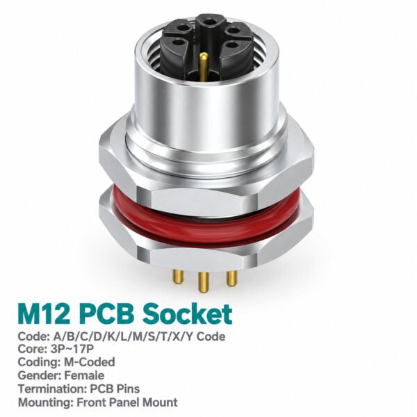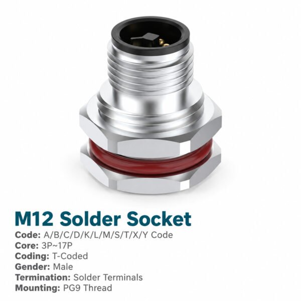
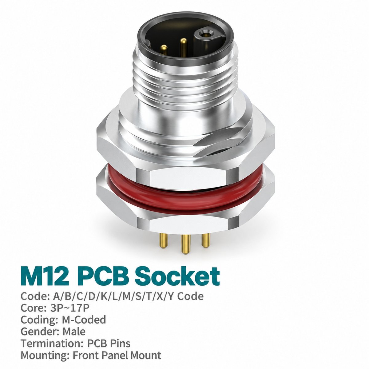
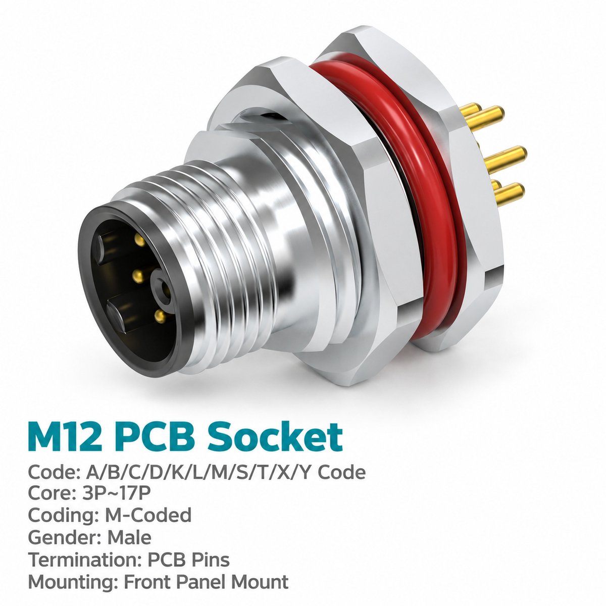
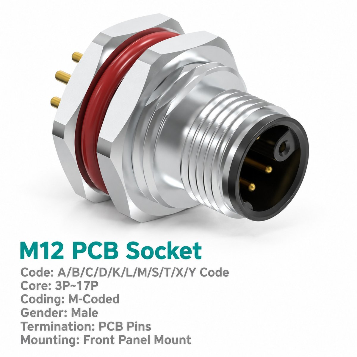
Xmost M12 M-coded male front mount PCB connector provides a detachable AC power interface between an external female cable connector and the equipment’s internal circuit board. Its straight rear contacts support PCB insertion and dip soldering, combining a panel-mounted cable connection with direct board termination.
Four contact arrangements provide two, three, four or five circuit contacts plus protective earth. Each configuration carries catalogue ratings of 8 A and 630 V, allowing the contact count to be selected according to the equipment’s circuit requirements.
This front fastened M12 panel mount power connector is available with PG9 or M16 × 1.5 mounting threads. Match the M-coded interface and contact arrangement to the female cable connector, then use the front mount outline to check enclosure clearance and board position.
Key Features
- 8 A / 630 V AC power interface: Listed ratings for all four configurations.
- Four arrangements with PE: Choose 2+PE, 3+PE, 4+PE or 5+PE.
- Male M-coded connection: Mates with a compatible M12 M-coded female power cable connector.
- Front fastened construction: Integrates the power interface into the equipment panel.
- Straight PCB contacts: Supports insertion and dip-solder termination.
- PG9 or M16 × 1.5 mounting: Two panel thread options in unshielded construction.
Product Dimensions
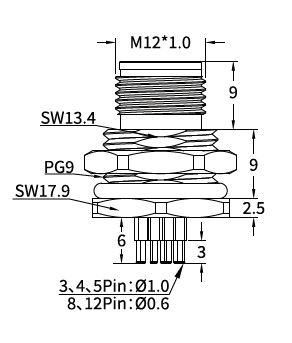
[Insert the male front mount outline drawing and corresponding panel cut-out drawing from page 20.]
Illustrated PG9 Front Mount Version — Dimensions in mm
| Item | Drawing Value |
|---|---|
| Mating thread | M12 × 1.0 |
| Panel mounting thread shown | PG9 |
| Upper axial section | 9 |
| Middle axial section | 9 |
| Lower axial section | 2.5 |
| Upper wrench size | SW13.4 |
| Mounting nut wrench size | SW17.9 |
| Rear contact section | 6 |
| Contact tip section | 3 |
| PCB contact diameter indicated for 3 / 4 / 5-pin versions | Ø1.0 |
The outline drawing does not separately specify the 6-pin PCB contact diameter.
Needle Arrangement (Front View)

[Insert the M-coded male needle arrangement diagrams for 3-pin (2+PE), 4-pin (3+PE), 5-pin (4+PE) and 6-pin (5+PE) from page 20.]
| Total Contacts | Arrangement |
|---|---|
| 3 pins | 2+PE |
| 4 pins | 3+PE |
| 5 pins | 4+PE |
| 6 pins | 5+PE |
The diagrams show the male mating-face view. Match the numbered contacts and PE position to the selected female connector and equipment power schematic.
Product Specifications
| Parameter | Specification |
|---|---|
| Product type | M12 M-coded male front mount PCB AC power connector |
| Mounting | Front fastened |
| Contact arrangements | 2+PE / 3+PE / 4+PE / 5+PE |
| PCB contact style | Straight |
| Termination | PCB dip soldering |
| Standard listed | IEC 61076-2-111 |
| Rated current | 8 A |
| Rated voltage | 630 V |
| Shielding | Unshielded |
| Mating thread | M12 × 1.0 |
| Panel mounting threads | PG9 / M16 × 1.5 |
| Insulation resistance | ≥100 MΩ |
| Contact resistance | ≤5 mΩ |
| Recommended coupling torque | 0.4 N·m |
| Maximum coupling torque | 0.8 N·m |
| Temperature range, flexible use | −25°C to +80°C |
| Temperature range, static use | −40°C to +80°C |
| Protection ratings listed | IP67 / IP68 |
| Pollution degree | 3 |
| Insulator materials listed | PA66+GF / TPU+GF |
Applications
- Industrial AC power modules: Connects external power cables to internal PCB circuits.
- Automation control equipment: Provides a multi-contact power interface with protective earth.
- Machine electronics housings: Integrates a front mount M12 power connector into the enclosure.
- Modular electrical assemblies: Combines detachable cable connection with PCB termination.
Selection and Ordering
| Contact Arrangement | PG9 Mounting | M16 × 1.5 Mounting |
|---|---|---|
| 3-pin — 2+PE | 1M1207MM2EHP9WP | 1M1207MM2EH16WP |
| 4-pin — 3+PE | 1M1207MM3EHP9WP | 1M1207MM3EH16WP |
| 5-pin — 4+PE | 1M1207MM4EHP9WP | 1M1207MM4EH16WP |
| 6-pin — 5+PE | 1M1207MM5EHP9WP | 1M1207MM5EH16WP |
Example enquiry: M12 M-coded male front mount PCB power connector, 5-pin (4+PE), 8 A, 630 V AC, PG9 mounting, part number 1M1207MM4EHP9WP.