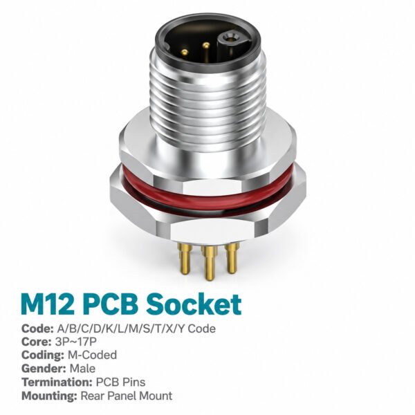
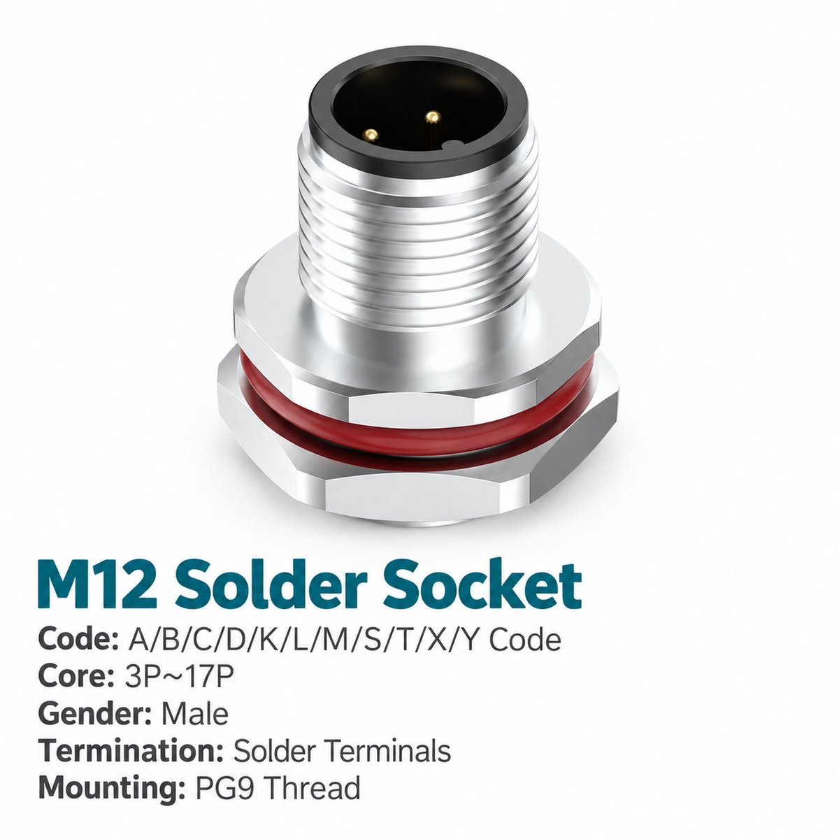
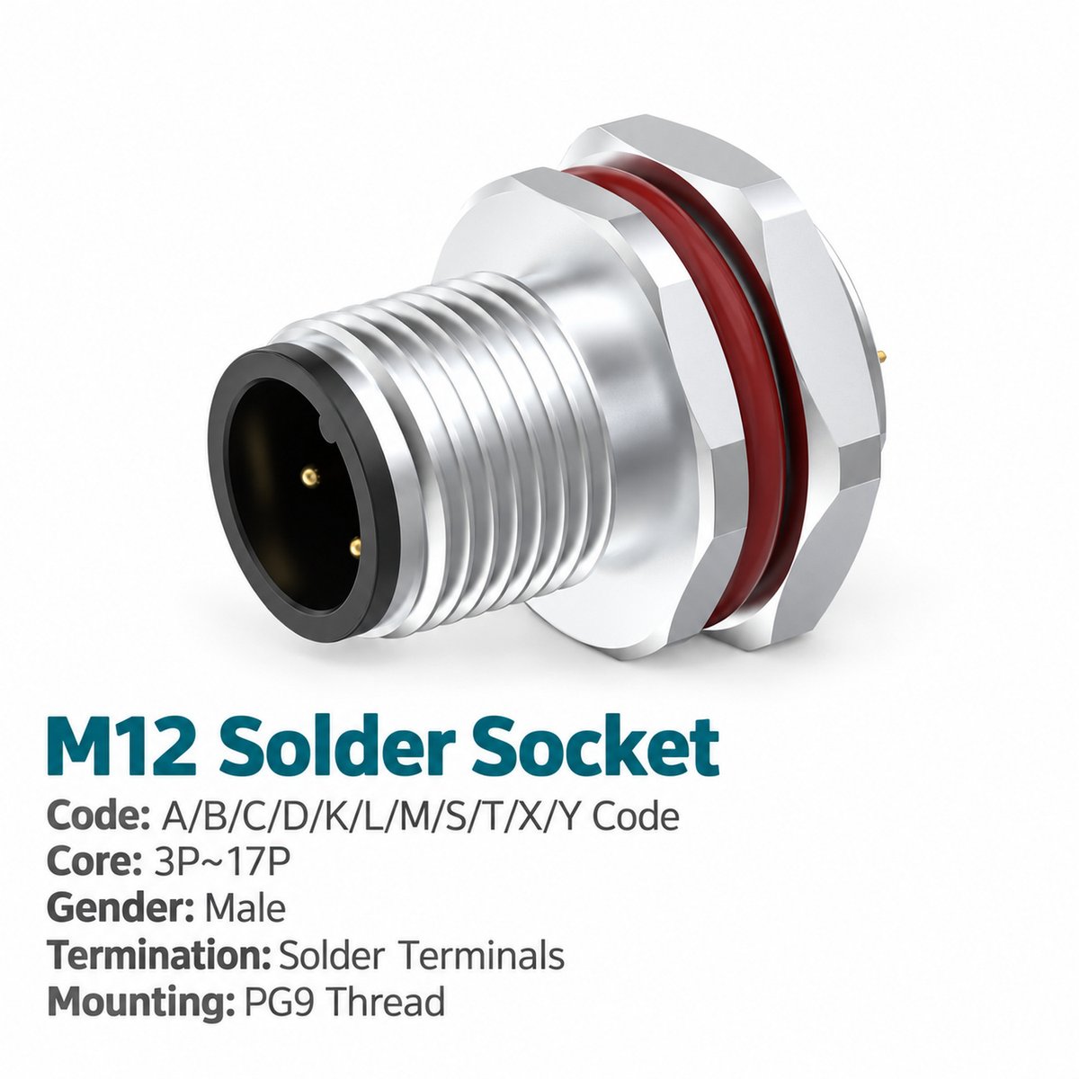
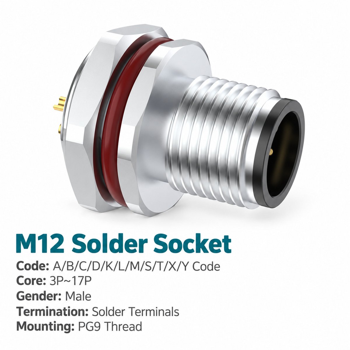
M12 A-coded male rear mount socket connects a compatible external female cable connector to the equipment’s internal harness. Select the rear fastened version when the enclosure provides mounting access and clearance for the rear hardware.
The unwired M12 male solder socket allows termination during harness assembly. The 0.3 m pre-wired version provides leads for routing to an internal terminal or circuit connection.
Choose the contact count according to the required conductors, then check its current, voltage and wire size. A higher contact count has different electrical ratings, so the selected configuration must match the equipment circuit.
Key Features
- Rear fastened installation: For panels designed around a rear mount receptacle.
- Male A-coded connection: Mates with a compatible M12 A-coded female connector.
- 3–17 pin selection: Six contact counts for different wiring requirements.
- Solder wiring interface: Supports termination to the internal harness.
- Unwired or 0.3 m leads: Choose the wiring option suited to assembly.
- Three mounting threads: M12 × 1.0, PG9 and M16 × 1.5 versions.
- Threaded coupling: M12 × 1.0 mating connection.
- Unshielded design: As listed for this catalogue product.
Product Dimensions
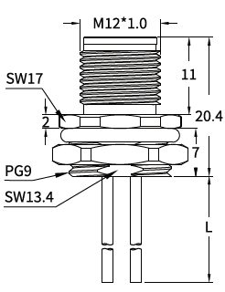
[Insert the rear mount male socket drawing and panel cut-out drawing here.]
Illustrated PG9 Version — Dimensions in mm
| Item to Check | Drawing Value |
|---|---|
| Mating thread | M12 × 1.0 |
| Panel mounting thread | PG9 |
| Overall body length shown, excluding leads | 20.4 |
| Upper axial section shown | 11 |
| Flange thickness shown | 2 |
| Lower axial section shown | 7 |
| Upper wrench size | SW17 |
| Lower wrench size | SW13.4 |
| Lead length | L; according to ordered version |
Allow space for rear fastening hardware and internal wire routing. Prepare the panel opening using the drawing for the selected mounting thread.
Needle Arrangement (Front View)

[Insert the A-coded male needle arrangement screenshot showing all six pin counts.]
The contact diagrams are viewed from the mating face. Check the selected arrangement against the equipment schematic and external cable connector.
For the 3-pin version, the populated positions are 1, 3 and 4.
Product Specifications
| Parameter | Specification |
|---|---|
| Product type | M12 A-coded male rear mount socket |
| Mounting | Rear fastened |
| Termination | Solder |
| Wiring options | Unwired / 0.3 m pre-wired leads |
| Standard listed | IEC 61076-2-101 |
| Shielding | Unshielded |
| Coupling thread | M12 × 1.0 |
| Panel mounting thread options | M12 × 1.0 / PG9 / M16 × 1.5 |
| Insulation resistance | ≥100 MΩ |
| Contact resistance | ≤5 mΩ |
| Recommended coupling torque | 0.4 N·m |
| Maximum coupling torque | 0.8 N·m |
| Temperature range, flexible use | −25°C to +80°C |
| Temperature range, static use | −40°C to +80°C |
| Protection ratings listed | IP67 / IP68 |
| Pollution degree | 3 |
| Insulator materials listed | PA66+GF / TPU+GF |
Electrical Ratings by Contact Count
| Contacts | Rated Current | Rated Voltage | Wire Size Listed |
|---|---|---|---|
| 3 pins | 4 A | 250 V | 0.34 mm² / AWG22 |
| 4 pins | 4 A | 250 V | 0.34 mm² / AWG22 |
| 5 pins | 4 A | 60 V | 0.34 mm² / AWG22 |
| 8 pins | 2 A | 30 V | 0.25 mm² / AWG24 |
| 12 pins | 1.5 A | 30 V | 0.14 mm² / AWG26 |
| 17 pins | 1.5 A | 30 V | 0.14 mm² / AWG26 |
Applications
This M12 A-coded rear mount panel connector can be considered for:
- Machine sensor connections: Linking external cables to internal input circuits.
- Actuator wiring interfaces: Providing a detachable connection within the selected electrical ratings.
- Control enclosures with rear mounting access: Accommodating hardware and harness wiring behind the panel.
- Pre-wired equipment assemblies: Routing socket leads to an internal terminal or circuit.
- Multi-contact signal interfaces: Selecting additional contacts where the equipment wiring requires them.
Wiring and Lead Options
[Insert the wire colour and pin assignment table from page 1 here.]
Choose the unwired version for solder termination during assembly or the 0.3 m pre-wired version for connection to the internal harness.
The 4-pin version uses:
| Contact | Wire Colour |
|---|---|
| Pin 1 | Brown — BN |
| Pin 2 | White — WH |
| Pin 3 | Blue — BU |
| Pin 4 | Black — BK |
Follow the corresponding catalogue table for other pin counts and the equipment schematic for circuit assignments.
Selection and Ordering
| Selection Item | Available Choices |
|---|---|
| Contact count | 3 / 4 / 5 / 8 / 12 / 17 pins |
| Mounting style | Rear mount |
| Panel mounting thread | M12 × 1.0 / PG9 / M16 × 1.5 |
| Wiring | Unwired / 0.3 m pre-wired |
| Custom requirements | Specify wire type or lead length |
Example enquiry: M12 A-coded male rear mount socket, 8-pin, solder termination, M16 × 1.5 mounting, unwired.