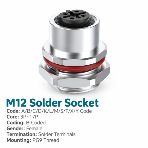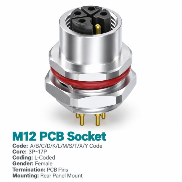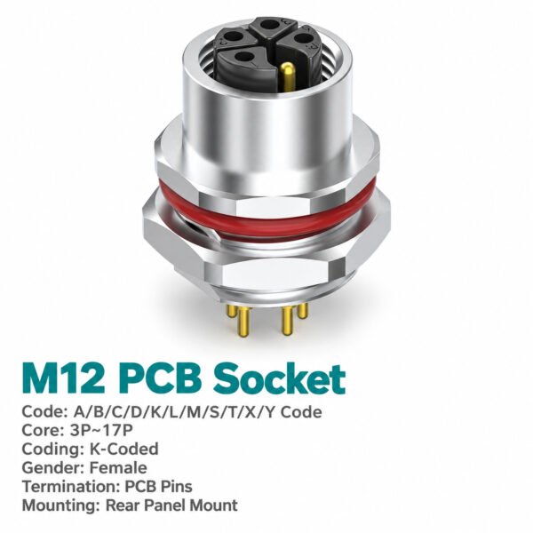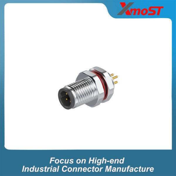
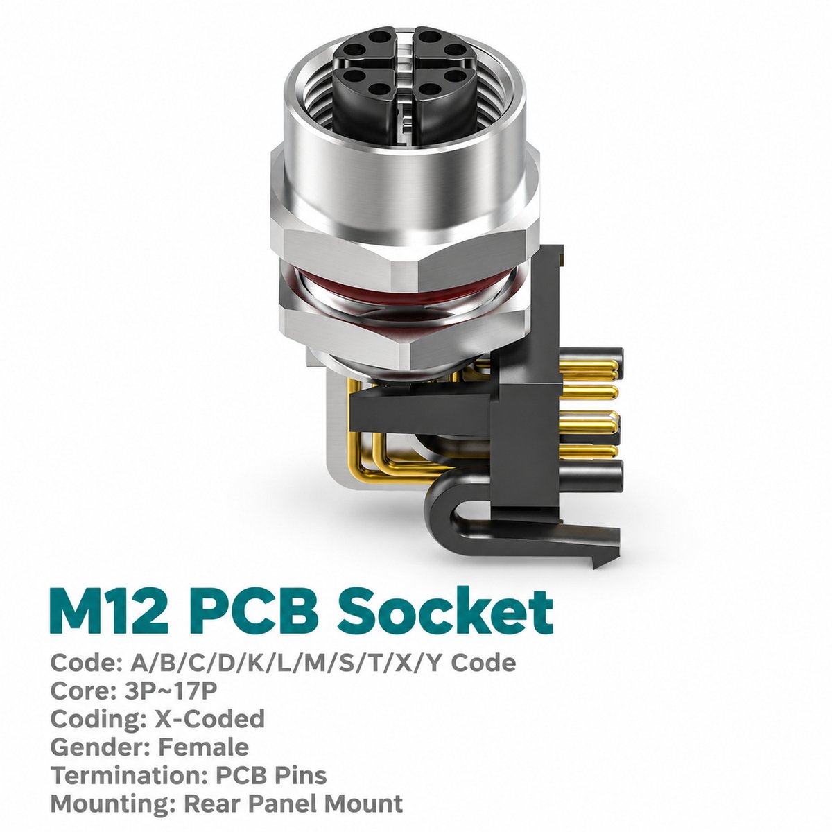


Xmost M12 X-coded female rear mount right angle PCB socket links an external Ethernet cable assembly to the circuit board inside industrial network equipment. Its female X-coded interface mates with a compatible 8-pin male cable connector, while bent contacts provide the PCB dip-solder connection.
Designed for rear fastened installation, this M12 panel mount Ethernet socket combines a threaded external connection with a 90-degree board termination. The rear mount outline defines the dimensions needed to position the socket within the enclosure and check clearance around the contact assembly.
The connector is supplied in shielded construction. Its shielding connection, mating cable and board routing should be considered together when designing the complete industrial Ethernet interface.
Key Features
- Rear fastened installation: For equipment housings designed around a rear mount panel socket.
- Female X-coded connection: Accepts compatible 8-pin M12 X-coded male cable connectors.
- 90-degree PCB termination: Bent contacts connect the panel interface to the internal circuit board.
- Shielded construction: Provides a shielded Ethernet connector interface.
- PCB dip-solder contacts: Supports board insertion and soldered termination.
- M12 threaded mating: M12 × 1.0 cable connection.
Product Dimensions
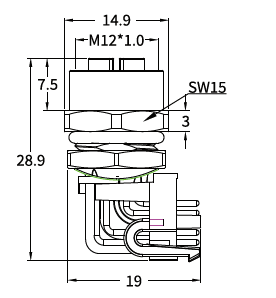
[Insert the female right angle rear mount outline drawing and corresponding panel cut-out drawing from page 23.]
Dimensions in mm
| Item | Drawing Value |
|---|---|
| Mating thread | M12 × 1.0 |
| Panel mounting thread shown | M12 × 1.0 |
| Overall vertical dimension shown | 28.9 |
| Horizontal dimension shown | 19 |
| Upper body width shown | 14.9 |
| Upper axial section shown | 7.5 |
| Mounting nut wrench size | SW15 |
| Flange section shown | 3 |
| Recommended panel dimension A | 10.5, +0.1/−0 |
| Recommended panel dimension B | 12, +0.1/−0 |
| Maximum panel thickness indicated | 2.0 |
| Panel edge chamfer shown | C0.5 |
Needle Arrangement (Front View)

[Insert the X-coded 8-pin female needle arrangement diagram from page 23.]
The diagram shows the female connector from the mating face, with contacts numbered 1–8. Match this arrangement to the external male connector and use the equipment wiring specification for network signal assignments.
Product Specifications
| Parameter | Specification |
|---|---|
| Product type | M12 X-coded female rear mount right angle PCB Ethernet socket |
| Mounting | Rear fastened |
| Contact count | 8 pins |
| PCB contact style | Right angle / 90-degree |
| Termination | PCB dip soldering |
| Standard listed | IEC 61076-2-109 |
| Rated current | 0.5 A |
| Rated voltage | 50 V AC / 60 V DC |
| Shielding | Shielded |
| Mating thread | M12 × 1.0 |
| Panel mounting thread shown | M12 × 1.0 |
| Insulation resistance | ≥100 MΩ |
| Contact resistance | ≤5 mΩ |
| Recommended coupling torque | 0.4 N·m |
| Maximum coupling torque | 0.8 N·m |
| Temperature range, flexible use | −25°C to +80°C |
| Temperature range, static use | −40°C to +80°C |
| Protection ratings listed | IP67 / IP68 |
| Pollution degree | 3 |
| Insulator materials listed | PA66+GF / TPU+GF |
Applications
- Industrial network modules: Connects external Ethernet cables to PCB communication circuits.
- Ethernet switches and gateways: Provides a shielded X-coded cable interface where specified by the equipment design.
- Machine control enclosures: Suits rear fastened panels with right angle board connections.
- Modular automation equipment: Integrates a detachable 8-pin network connection into the housing.
Selection and Ordering
| Selection Item | Specification |
|---|---|
| Interface | M12 X-coded female, 8-pin |
| Mounting | Rear mount |
| PCB termination | Right angle, dip soldering |
| Shielding | Shielded |
| Part number | 1M1211XF08R12PS |
Example enquiry: M12 X-coded female rear mount right angle PCB Ethernet socket, 8-pin, shielded, part number 1M1211XF08R12PS.